Apparatus and method for transmitting and receiving data streams in wireless system

a wireless system and data stream technology, applied in the field of wireless systems, can solve the problems of limited capacity and limited scheme in terms of achievable statistical multiplexing gain, and achieve the effect of high signaling overhead and limited capacity

Inactive Publication Date: 2014-03-20
SAMSUNG ELECTRONICS CO LTD
View PDF4 Cites 3 Cited by
  • Summary
  • Abstract
  • Description
  • Claims
  • Application Information

AI Technical Summary

Benefits of technology

[0011]Another aspect of the present invention provides an apparatus and method for transmitting and receiving data streams in a wireless system, to solve the problems that the conventional scheme may suffer from limited capacity, due to short physical slot duration and high signaling overhead, and may be limited in terms of multiplexing gain, due to the limited capacity.

Problems solved by technology

However, such a scheme, in which the signaling information is arranged in each of the physical slots, may suffer from limited capacity, due to short physical slot duration and high signaling overhead.
Furthermore, such a scheme may be limited in terms of achievable statistical multiplexing gain, due to the limited capacity that may be achieved.

Method used


Image

  • Apparatus and method for transmitting and receiving data streams in wireless system
  • Apparatus and method for transmitting and receiving data streams in wireless system
  • Apparatus and method for transmitting and receiving data streams in wireless system

Examples


first embodiment

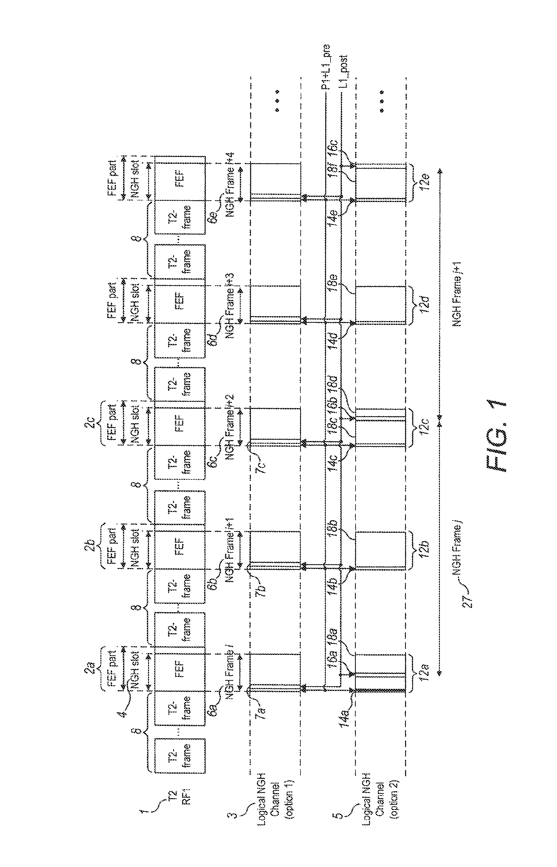
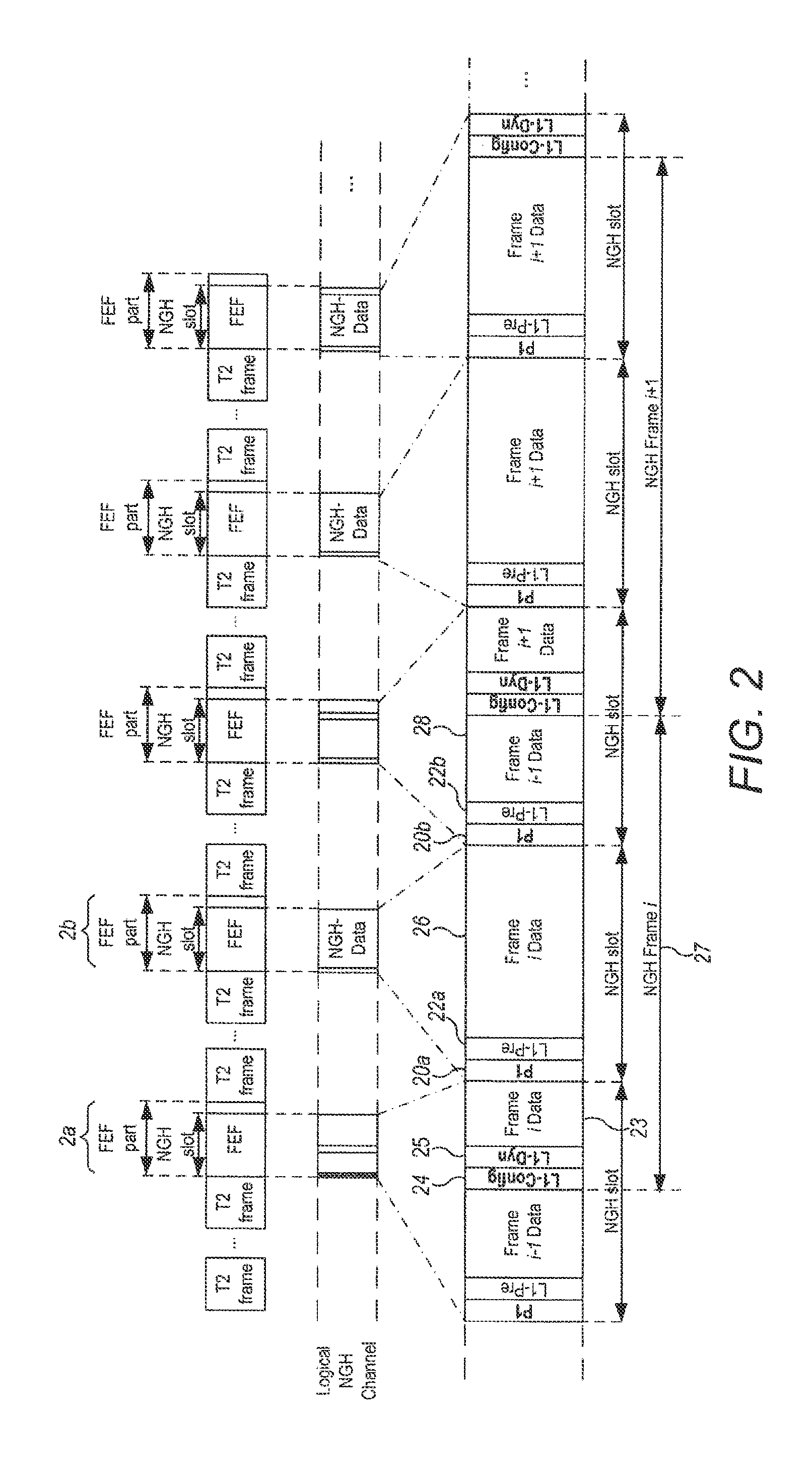
[0038]In the present invention, as illustrated by FIG. 1 as “Option 2”5 and by FIG. 2, a logical NGH frame 27 is configured in two or more FEF slots 2a, 2b and 2c, so that the length of the logical NGH frame 27 may be greater than the length of a FEF slot 2a, 2b. In other words, one logical NGH frame may be configured by combining the data transmitted in two or more FEF slots, and this may be expressed as FEF bundling. In this case, the ratio of signaling information for signaling overhead and data capacity may be reduced compared to the case where the length of logical NGH frame is limited to the length of FEF slot, like “Option 1”3. In the case where they are transmitted over multiple Radio Frequency (RF) channels, the two or more FEF slots may be within a transmission sequence for different radio frequency channels and the logical frames may be arranged to have a constant length, even though the length of FEF slots may vary between the radio frequency channels. The length of the ...

second embodiment

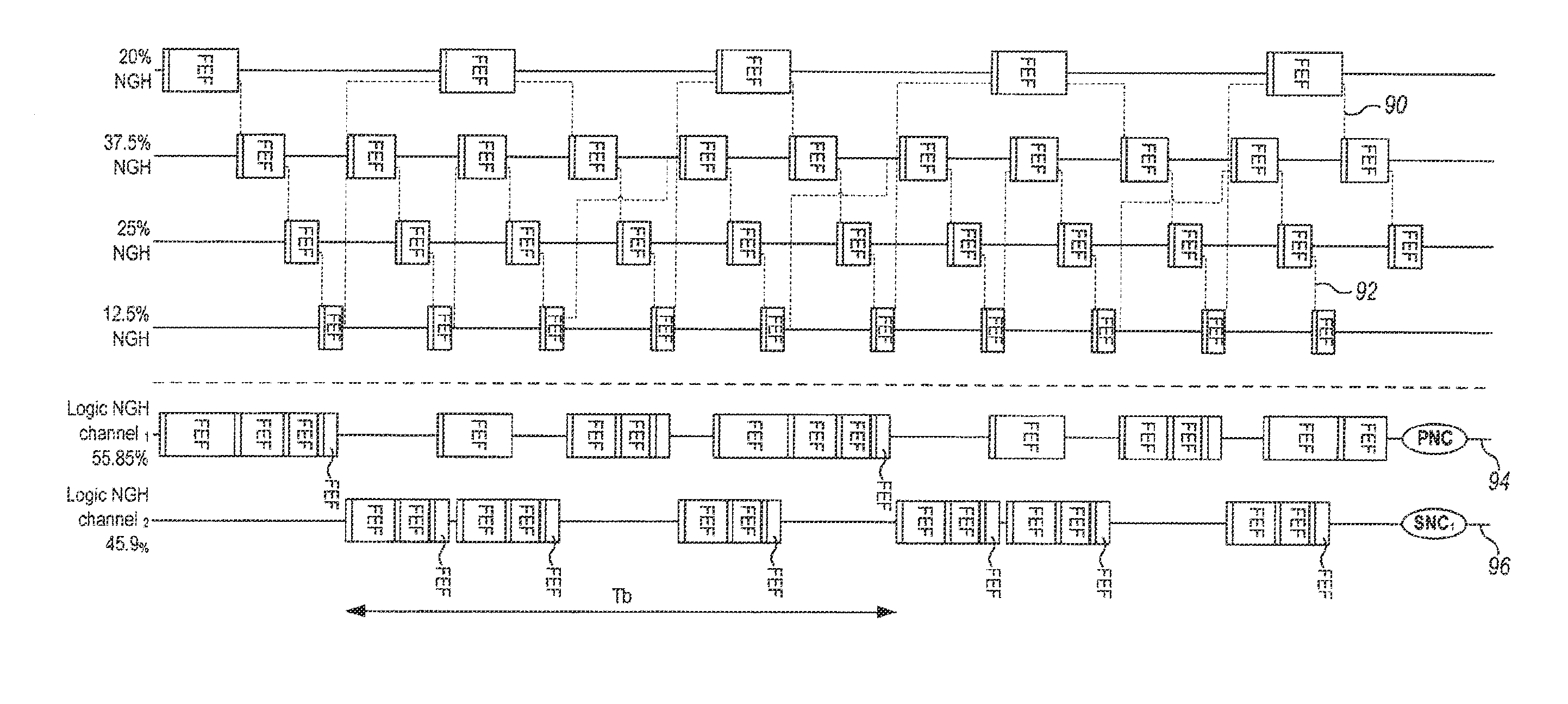
[0043]In embodiments of the present invention, NGH slots within a sequence of additional physical slots (FEF slots) are bundled together as described above to form a logical NGH channel for transmitting a set of data streams, and a series of logical NGH logical frames within a logical channel are mapped to the sequence of additional physical slots, for example, FEF slots. The sequence of logical NGH frames may be transmitted over one or more RF channels. If the sequence is transmitted over a single RF channel, then a tuner needs not to re-tune between additional physical slots in order to receive the sequence of logical NGH frames. However, if the sequence 30a . . . 30h of a logical NGH channel or a series of logical NGH frames is transmitted over multiple radio frequencies RF1, RF2, RF3 and RF4, i.e., is chosen to fall on several radio frequency channels, as in a second embodiment illustrated by FIG. 3, then a logical channel with a larger capacity may be formed, and also the logic...


PUM


Abstract

A method for transmitting data including a plurality of data streams in a wireless system is described. The method includes receiving one or more data streams; mapping the received data streams to at least one logical frame; mapping the logical frame to more than one additional physical slot; configuring each of the more than one additional physical slot includes signaling information for receiving the data streams; and transmitting at least one superframe including the more than one additional physical slot.

Description

PRIORITY[0001]This application is a Continuation Application of U.S. patent application Ser. No. 13 / 353,857, which was filed in the U.S. Patent and Trademark Office on Jan. 19, 2012, and claims priority under 35 U.S.C. §119(a) to Patent Applications filed in the United Kingdom Intellectual Property Office on Jan. 19, 2011 and assigned Serial No. GB 1100901.6, and Oct. 26, 2011 and assigned Serial No. GB 1118537.8, the content of each of which is incorporated herein by reference.BACKGROUND OF THE INVENTION[0002]1. Field of the Invention[0003]The present invention relates generally to wireless systems, and more specifically, but not exclusively, to a method and apparatus relating to transmission and reception of data streams in digital video broadcast systems.[0004]2. Description of the Related Art[0005]A wireless system, such as a digital video broadcasting system, may transmit data in the form of a sequence of frames arranged in a frame structure. A digital video broadcasting system...

Claims


Application Information

Patent Timeline
Patent Type & Authority Applications(United States)
IPC IPC(8): H04L5/00
CPCH04L27/2656H04L27/2605H04L5/0037H04L5/0048H04N21/236H04L5/0007H04L5/0091H04W28/06H04N21/23614H04N21/2385H04W74/04H04L5/0044H04L65/61H04L65/70H04W72/0446
Inventor MOURAD, ALAINGUTIERREZ, ISMAEL
Owner SAMSUNG ELECTRONICS CO LTD
Why Eureka
Try Eureka