Sonar imaging

a sonar imaging and imaging technology, applied in image data processing, acoustic wave reradiation, measurement devices, etc., can solve the problems of large drop in the probability of detection, time-consuming and subject to human error, etc., and achieve the effect of reducing computation requirements

Inactive Publication Date: 2014-03-20
SEEBYTE
View PDF14 Cites 11 Cited by
  • Summary
  • Abstract
  • Description
  • Claims
  • Application Information

AI Technical Summary

Benefits of technology

[0014]The method may involve using the normalised image to define a plurality of skewed integral images, each for a different skew angle, and applying the multiple templates for the multiple test objects to the skewed ...

Problems solved by technology

This is time consuming and subject to human error.
Particularly with supervised filter response algorithms, a small ...

Method used


Image

  • Sonar imaging
  • Sonar imaging
  • Sonar imaging

Examples


Embodiment Construction

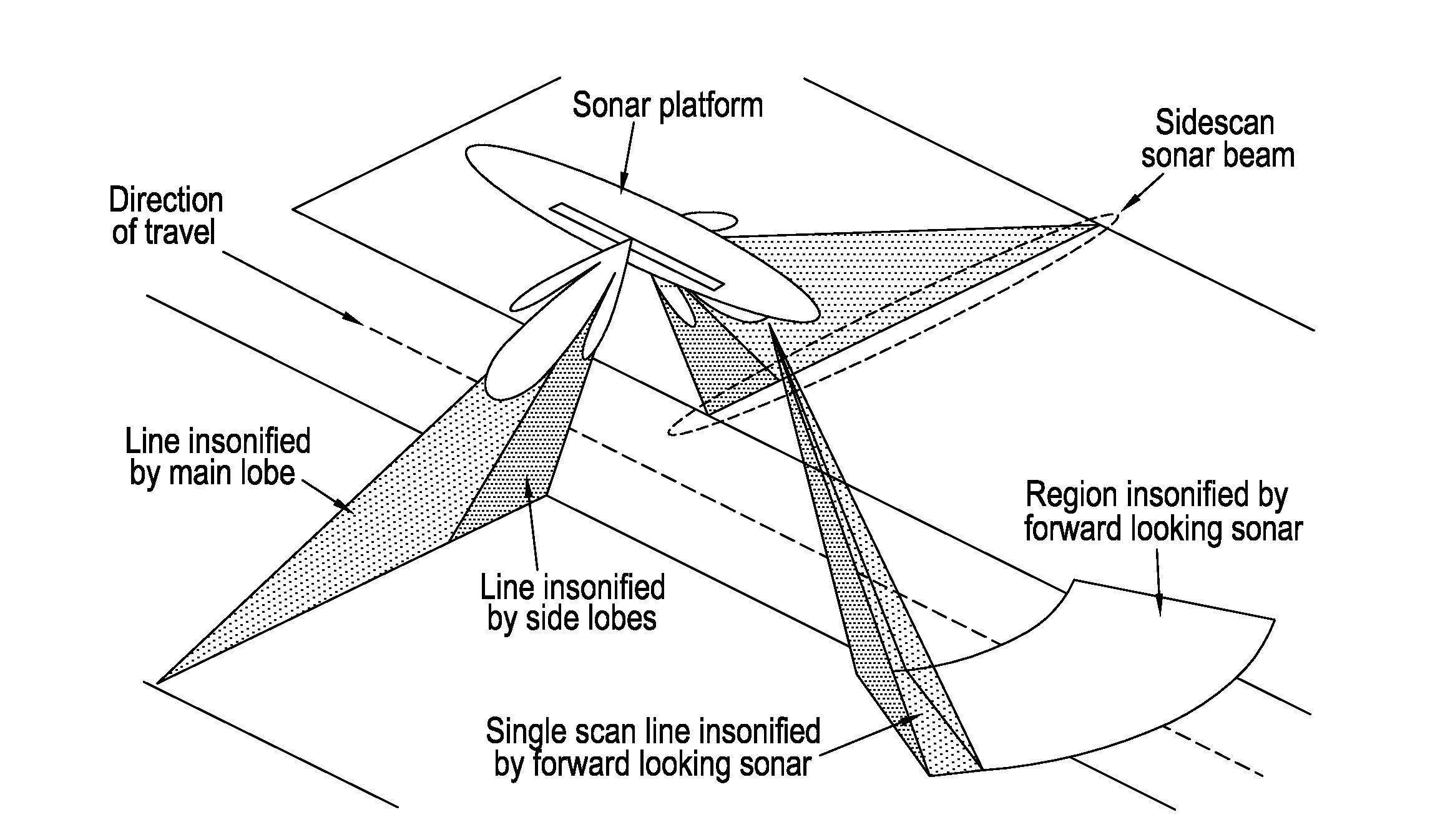
[0031]The present invention is applicable to sonar imaging. Sonar imaging uses sensors which have imaging geometries where: the emitter can be approximated as a point source; the emitter illuminates or insonifies the object at a known grazing angle; the object is located on a planar surface; and the angle from the imaging sensor to the planar surface is known. Examples of sensors displaying this geometry are sidescan sonar and forward looking sonar.

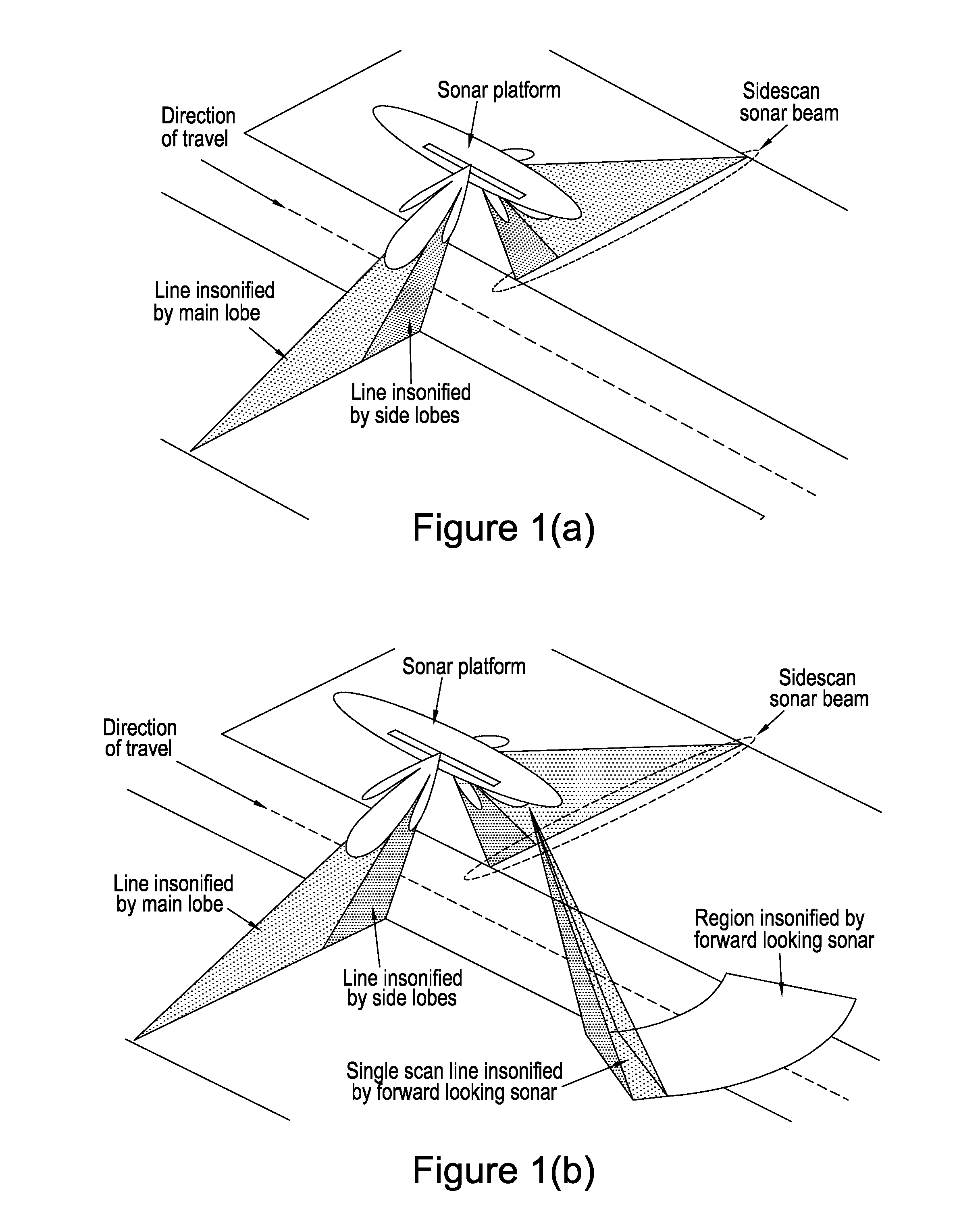
[0032]FIG. 1(a) shows a sidescan sonar sensor system. In this, sensors are mounted on the side of an underwater vehicle. They comprise an array of transducers mounted parallel to the direction of motion. Sidescan sonar sensors generate a fan shaped acoustic beam perpendicular to the direction of motion and the sea-floor. The intensity of the acoustic return from the sea floor, objects, and other scatters are integrated by their time of flight to determine the intensity of a pixel. The pixels ordered by time of flight form an intensity ima...


PUM


Abstract

A method for recognising a target in a sonar image, the method comprising: normalising a sonar image; using/defining multiple test objects; rotating each test object between multiple positions; using a projection of each test object in each position as a template, so that multiple templates are provided for each test object, each template corresponding to a different rotational position; applying the multiple templates for the multiple test objects to the normalised image; and creating at least one feature vector for the image for use in target recognition.

Description

CROSS-REFERENCE TO RELATED APPLICATION[0001]This application claims priority to and the benefit of United Kingdom Application No. 1216659.1, filed Sep. 18, 2012, the entire disclosure and contents of which is hereby incorporated by reference herein.BACKGROUND[0002]1. Technical Field[0003]The present invention relates to sonar imaging, and in particular sidescan sonar and forward looking sonar imaging.[0004]2. Related Art[0005]Sidescan Sonar (SSS) is used for surveying large areas of the sea floor for sea bottom targets. Side-scan sonar uses a device that emits sonar pulses down toward the seafloor across a narrow angle perpendicular to the path of the sensor through the water. Reflections from the seafloor are recorded in across-track slices. When stitched together along the direction of motion, these slices form an amplitude image of the seafloor within the beam coverage.[0006]Forward Looking Sonar (FLS) is used to provide a real time view of the seafloor in front of the vehicle. T...

Claims


Application Information

Patent Timeline
IPC IPC(8): G06T7/00
CPCG06T7/0044G01S7/539G01S15/89G06T7/74G01S15/8902
Inventor DANIELL, OLIVER
Owner SEEBYTE
Why Eureka
Try Eureka