Devices, systems, and methods for variable flow rate fuel ejection

Active Publication Date: 2014-03-20
UNIVERSITY OF DELAWARE
View PDF3 Cites 17 Cited by
  • Summary
  • Abstract
  • Description
  • Claims
  • Application Information

AI Technical Summary

Benefits of technology

This patent is about devices and methods for variable flow rate fuel ejection. One embodiment is a variable flow rate ejector that can adjust the flow rate of fluid and speed of sound in order to control the flow of fuel in a fuel cell system. Another aspect is a closed-loop fuel cell system that utilizes the ejector to recirculate hydrogen gas inside the system. The technical effects of this patent include increased efficiency of fuel cell systems and improved control over fuel flow.

Problems solved by technology

Hydrogen fuel cells generally do not consume all the hydrogen or oxygen supplied to them, as this would allow liquid water and inert gases to accumulate in the areas of the cell that are close to the end of the gas channel, resulting in severe performance loss due to low reactant concentration.
The design and operation of such mechanical pumps or blowers, however, is a serious engineering challenge, because the moist hydrogen in fuel cell systems corrodes many common materials (impervious materials are generally limited and / or costly), and the moving parts cannot be lubricated with any oil or grease that might contaminate the fuel cell stack.
In addition, such devices require substantial energy to operate, and thus increase the balance-of-plant load, decreasing the overall efficiency of the fuel cell system.
The ejector described in the above-described application, however, may only perform adequately or optimally at a specific gas flow rate or within a relatively small range of flow rates.

Method used


Image

  • Devices, systems, and methods for variable flow rate fuel ejection
  • Devices, systems, and methods for variable flow rate fuel ejection
  • Devices, systems, and methods for variable flow rate fuel ejection

Examples


Embodiment Construction

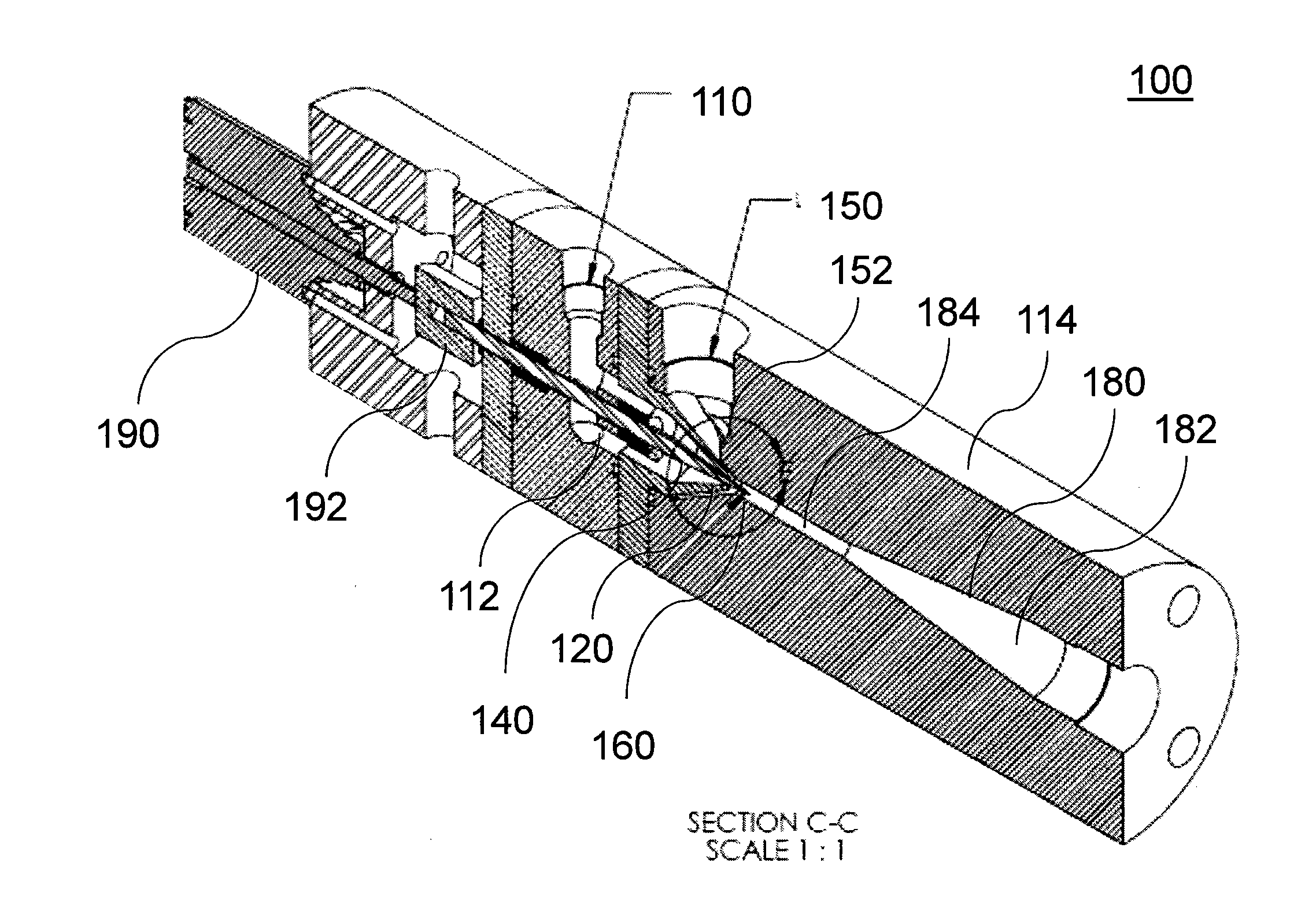
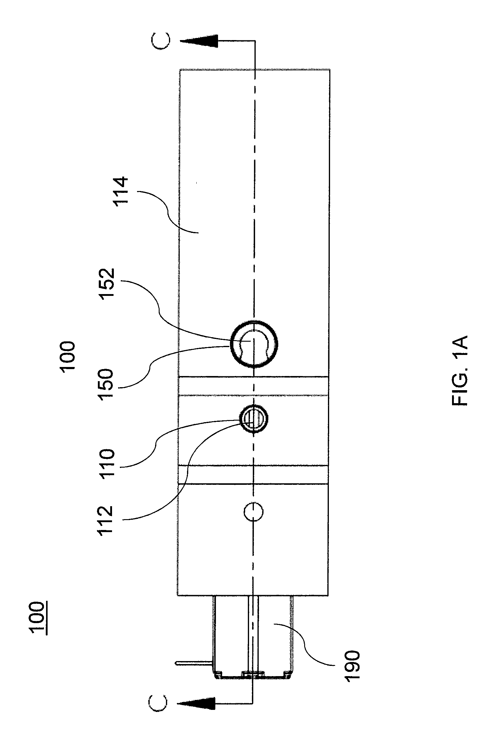
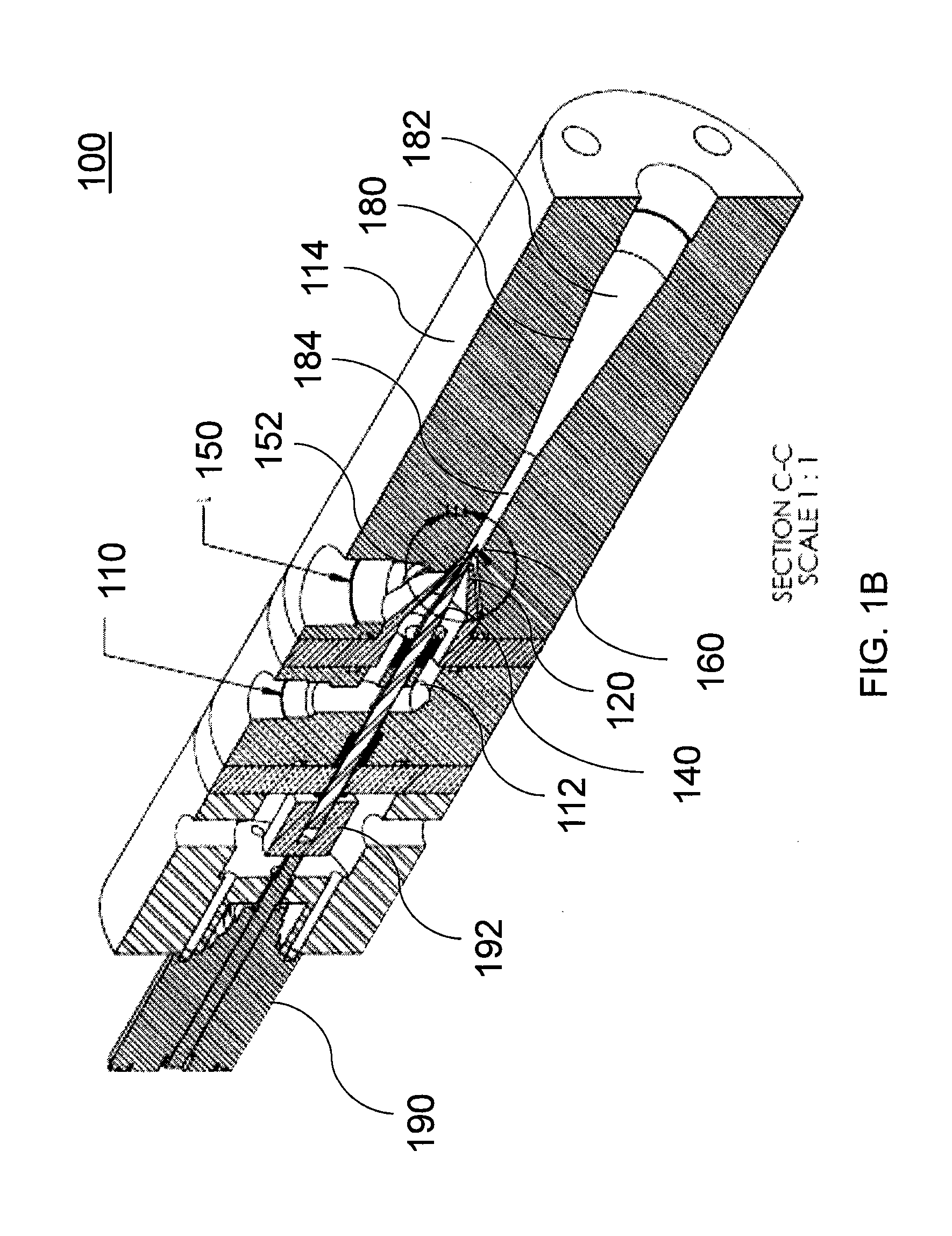
[0017]The various aspects of the present invention relate generally to devices, systems, and methods for various flow rate ejectors. Embodiments of the invention include a device adapted to be inserted into a fluid circulation system and control the is flow rate of the fluid in the circulation system.

[0018]The devices, systems, and methods described herein are particularly suitable for use in recirculation of hydrogen gas in hydrogen fuel cells. The disclosed systems may be particularly suited for maintaining an optimal flow rate and pressure between the gas outlet and the gas inlet of a fuel cell. Additional details regarding the control of flow rate will be described in greater detail herein.

[0019]While the invention is described herein primarily with respect to hydrogen gas recirculation, it will be understood that the invention is not so limited. The disclosed embodiments may be usable for variable flow rate control of fluids in any suitable system.

[0020]As set forth above, aspe...


PUM


Abstract

Devices, systems, and methods for variable flow rate fuel ejection are disclosed. A variable flow rate ejector comprises primary and secondary inlets, primary and secondary nozzles, and a needle. The primary nozzle is connected to receive a first fluid from the first inlet chamber and transmit the first fluid through a primary nozzle opening. The needle is disposed within the primary nozzle opening and is axially movable to vary an area of primary nozzle opening. The primary nozzle opening and the needle are sized to make the flow of the first fluid have a supersonic speed. The secondary inlet opens into a second inlet chamber positioned outside the primary nozzle to opening. A portion of the second fluid is entrained in the flow of the first fluid from the primary nozzle. The secondary nozzle opening is sized to make the flow of the first and second fluids have a subsonic speed.

Description

CROSS REFERENCE TO RELATED APPLICATIONS[0001]This application is the U.S. National Phase application of PCT International Application No. PCT / US2012 / 023703, filed Feb. 3, 2012, and claims priority to provisional application No. 61 / 439,143, filed Feb. 3, 2011, which applications are incorporated herein by reference in their entireties and for all purposes.STATEMENT REGARDING FEDERALLY SPONSORED RESEARCH[0002]The subject matter of the present invention was funded at least in part under Federal Transit Administration Grant No. DE-55-7001-00. The U.S. Government may have certain rights in this invention.FIELD OF THE INVENTION[0003]The present invention relates generally to fuel ejection, and more particularly, to devices, systems, and methods for variable flow rate fuel ejection.BACKGROUND OF THE INVENTION[0004]Hydrogen fuel cells generally do not consume all the hydrogen or oxygen supplied to them, as this would allow liquid water and inert gases to accumulate in the areas of the cell ...

Claims


Application Information

Patent Timeline
IPC IPC(8): F04F5/52H01M8/04
CPCF02M21/0206F04F5/466H01M8/04097H01M8/04156H01M8/04388H01M8/04753F04F5/52H01M8/04164Y02E60/50
Inventor BRUNNER, DOUGLASBAJPAI, MANISH W.KINZEY, JOHN ADAM C.MARCKS, SHANEPRASAD, AJAY K.ADVANI, SURESH G.
Owner UNIVERSITY OF DELAWARE
Why Eureka
Try Eureka