Force Sensing Using Bottom-Side Force Map

a force map and force sensing technology, applied in the field of force sensing, can solve the problems of application program inability to provide functions, touch devices with less capabilities, and one or more difficulties for touch devices

Inactive Publication Date: 2014-03-27
APPLE INC
View PDF12 Cites 102 Cited by
  • Summary
  • Abstract
  • Description
  • Claims
  • Application Information

AI Technical Summary

Benefits of technology

[0010]In one embodiment, capacitive sensing can be determined using a first layer of indium tin oxide (ITO) and a second layer of ITO as a dual-layer capacitive element (sometimes collectively referred to as DITO). In alternative embodiments, capacitive sensing can be determined using a first layer of ITO as a self-capacitive element, with respect to a substantially conductive (such as metallic) second layer. When applied force occurs at a particular point [X, Y] on the cover glass, the device stack can be deformed near and around that point, with the effect that the capacitive sensor measures a change in capacitance at one or more points near and around that point. For example, the capacitive sensor can include a set of rows and columns, one set (such as the rows) providing a driver for voltage along selected ones of rows, and one set (such as the columns) providing a drain for voltage along selected ones of columns. This has the effect that the capacitive sensor can determine one or more locations where changes in capacitance occur. The touch device can determine, in response to the change in capacitance, an amount of applied force. For example, the touch device can use a processor or other computing device, with the effect of determining a location and amount of applied force.
[0011]In one embodiment, the compressible layer, or the set of compressible elements, can include a capacitive layer disposed between the first layer of ITO and the second layer of ITO can include an air gap, with the effect that capacitance is measured across the air gap. In one embodiment, the capacitive layer disposed between the first layer of ITO and the second layer of ITO can include a layer of pressure-sensitive adhesive (PSA), which can be either substantially transparent or translucent (if located above the OLED layer), or can alternatively be opaque or otherwise light-absorbent (if located below the OLED layer). In either such case, the capacitive layer has the effect of not interfering with operation of the display. Further, materials other than ITO may be used, such as silver nanowire and other transparent (or near-transparent) electrically conductive electrodes.

Problems solved by technology

Each of these examples, as well as other possible considerations, can cause one or more difficulties for the touch device, at least in that inability to determine an amount of force applied by the user when contacting the touch device might cause a GUI or an application program to be unable to provide functions that would be advantageous.
When such functions are called for, inability to provide those functions may subject the touch device to lesser capabilities, to the possible detriment of the effectiveness and value of the touch device.

Method used


Image

  • Force Sensing Using Bottom-Side Force Map
  • Force Sensing Using Bottom-Side Force Map
  • Force Sensing Using Bottom-Side Force Map

Examples


example force

[0056 Sensor

[0057]FIG. 3 shows a conceptual drawing of a force sensor including a dual-layer cover glass.

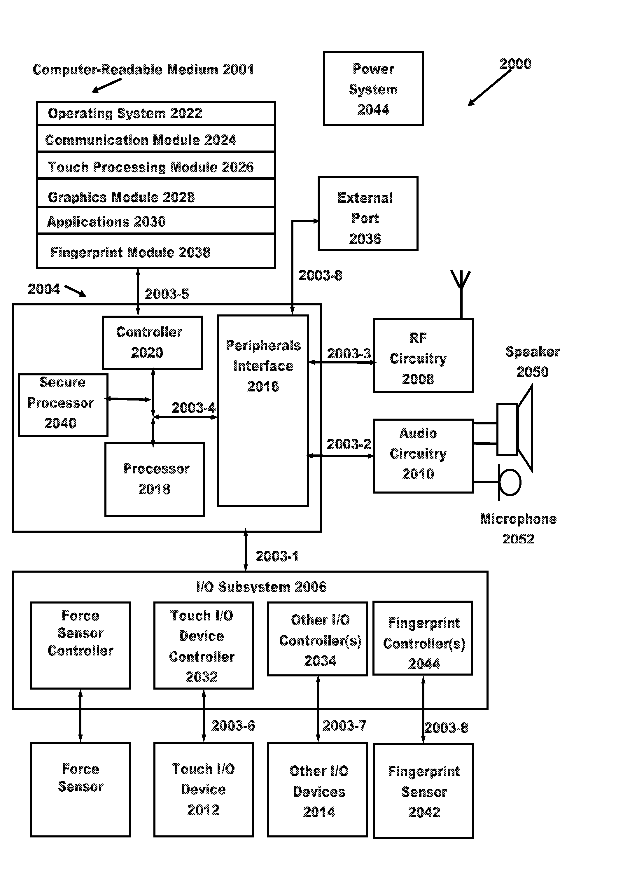
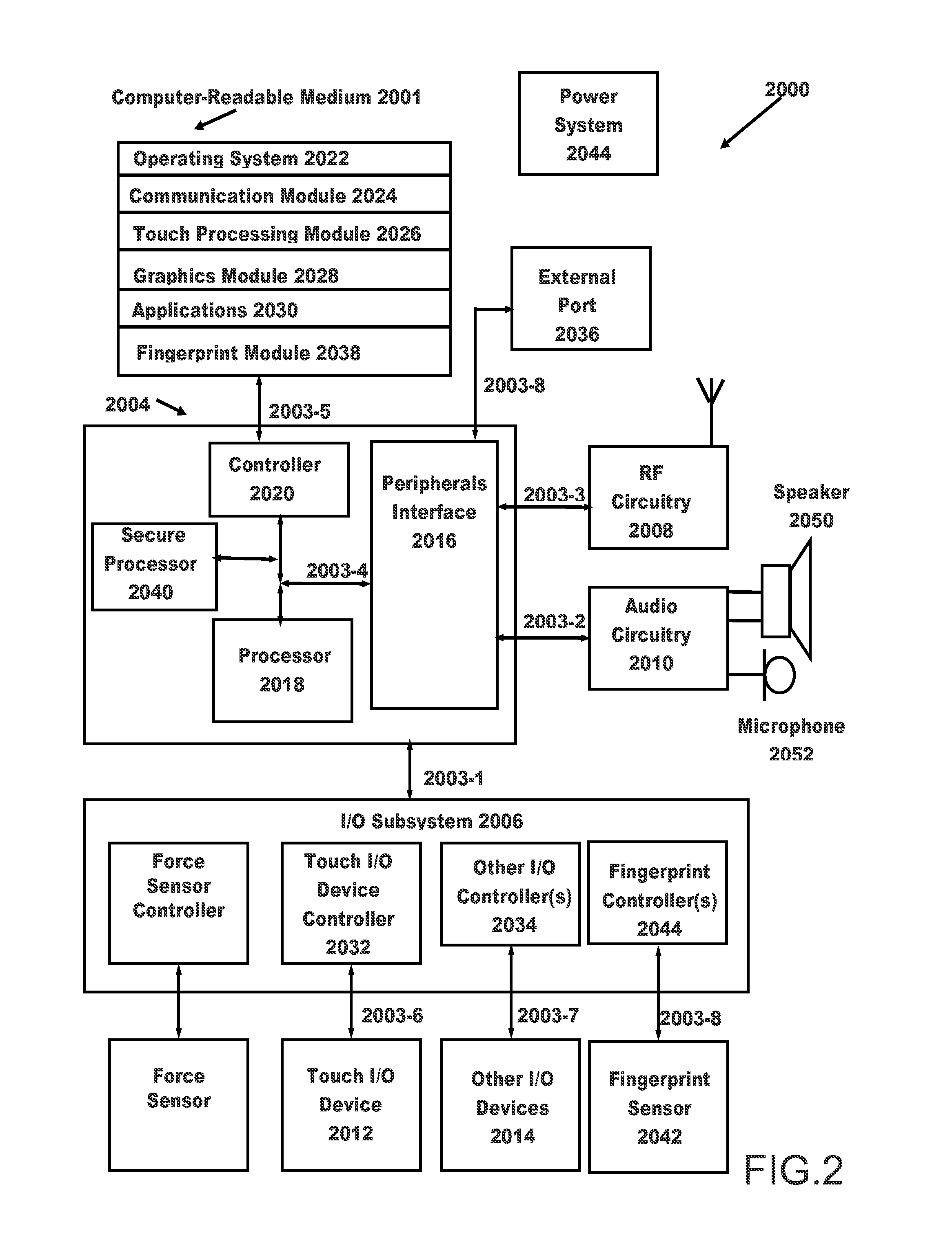
[0058]In one embodiment, the touch I / O device 2012 includes a frame 3010 and a midframe 3015 coupled to the frame 3010. The frame 3010 can be coupled to a spacer 3020, which is coupled to a cover glass (CG) 3025 and which can hold the cover glass (CG) 3025 substantially in place with respect to the frame 3010. In one embodiment, the cover glass (CG) 3025 can have approximately 500 microns of thickness.

[0059]In one embodiment, a device stack can be coupled below the cover glass (CG) 3025. In one embodiment, the touch I / O device 2012 can include a dual indium tin oxide (DITO) and pressure sensitive adhesive (PSA) layer 3030 positioned below the cover glass (CG) 3025. In one embodiment, the dual indium tin oxide (DITO) and pressure sensitive adhesive (PSA) layer 3030 can have approximately 378 microns of thickness. In one embodiment, the dual indium tin oxide (DITO) and pressure sen...


PUM

PropertyMeasurementUnit
Poisson's ratioaaaaaaaaaa
thicknessaaaaaaaaaa
thicknessaaaaaaaaaa

Abstract

A force sensor incorporated into a touch device, measuring deflection in a device stack, including compressible elements disposed between the device stack and the frame element. When the device stack is deformed, applied force is measured using the compressible elements, using capacitive sensing or strain measurements. The force sensitive sensor provides an applied force image for the touch device's surface. The applied force location [X, Y] can be determined from measures of cover glass tilt, force at particular points, and capacitive sensing of touch location.

Description

BACKGROUND[0001]1. Field of the Disclosure[0002]This application generally relates to force sensing in a touch device, and related matters.[0003]2. Background of the Disclosure[0004]Touch devices generally provide for identification of positions where the user touches the device, including movement, gestures, and other effects of position detection. For a first example, touch devices can provide information to a computing system regarding user interaction with a graphical user interface (GUI), such as pointing to elements, reorienting or repositioning those elements, editing or typing, and other GUI features. For a second example, touch devices can provide information to a computing system suitable for a user to interact with an application program, such as relating to input or manipulation of animation, photographs, pictures, slide presentations, sound, text, other audiovisual elements, and otherwise.[0005]It sometimes occurs that, when interfacing with a GUI, or with an applicatio...

Claims


Application Information

Patent Timeline
Patent Type & Authority Applications(United States)
IPC IPC(8): H03K17/975G06F3/041G09G3/32G01L1/00
CPCG06F3/044G06F2203/04105G06F3/0445G06F3/0447
Inventor HUPPI, BRIAN Q.LEUNG, OMAR SZELEONG, CRAIG CHRISTOPHERDRZAIC, PAUL STEPHEN
Owner APPLE INC
Why Eureka
Try Eureka