
Stereoscopic display with improved vertical resolution

a stereoscopic display and vertical resolution technology, applied in the field of pixel based 3d display, can solve the problems of losing half of the vertical resolution and increasing the cost of the display, and achieve the effect of improving the vertical resolution

Inactive Publication Date: 2014-03-27
KONINKLIJKE PHILIPS ELECTRONICS NV
View PDF3 Cites 5 Cited by
  • Summary
  • Abstract
  • Description
  • Claims
  • Application Information

AI Technical Summary

Benefits of technology

The invention describes a display technology that provides high resolution in both 2D and 3D modes. Instead of using polarizing stripes that overlay complete pixel rows, the technology uses sub-pixels that are compensated for by driving voltages determined by the color of the surrounding pixels. This leads to an apparent increase in resolution. The use of a fourth color that contributes significantly to the luminance of the pixel allows for the perception of even greater resolution. Combining sub-pixel rendering and multiple sub-pixels with a high luminance contribution improves the effect of perceived increased resolution.

Problems solved by technology

Consequently, half of the vertical resolution is lost.
This loss of resolution could be compensated by providing twice the amount of pixels, but that would make the display more expensive.

Method used


Image

  • Stereoscopic display with improved vertical resolution
  • Stereoscopic display with improved vertical resolution
  • Stereoscopic display with improved vertical resolution

Examples


Embodiment Construction

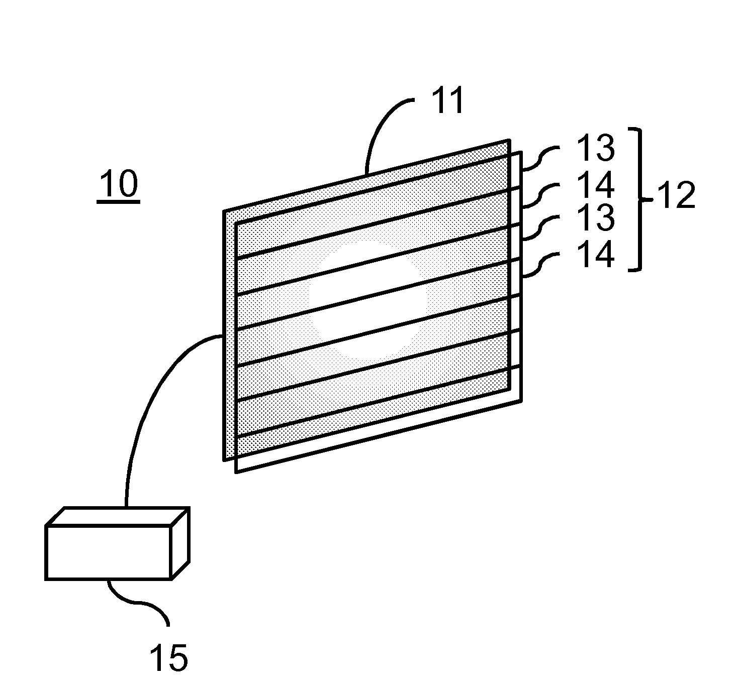
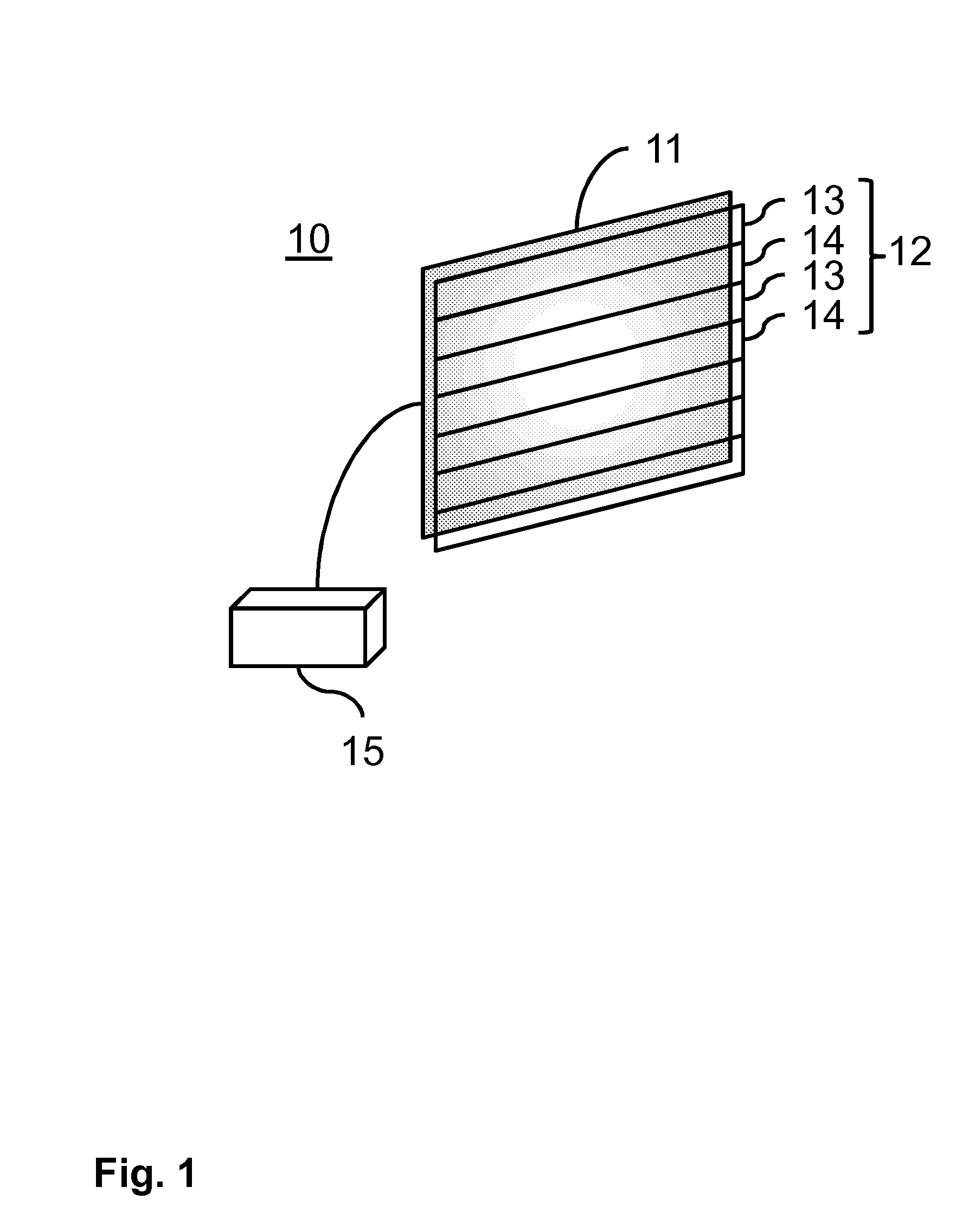
[0024]FIG. 1 shows a striped polarizer based 3D display 10. The display 10 comprises a display panel 11 with a plurality of systematically arranged pixels. The display panel 11 may, e.g., be a liquid crystal (LC) panel, a large array with LEDs of different colors or an OLED display. On top of the display panel a striped polarizer 12 is provided. The striped polarizer 12 comprises stripes 13, 14 of polarizing material, overlaying the pixel array. The polarizing material is transparent for letting through the light from the display panel 11. The striped polarizer 12 comprises an alternating pattern of left eye stripes 13 and right eye stripes 14.

[0025]Each stripe 13, 14 of polarizing material converts the incoming light from the display panel 11 to light with a well-defined polarization state. The polarization states may, e.g., be different linear or different circular polarization states. The left eye stripes 13 convert the light to a different polarization than the right eye stripe....


PUM


Abstract

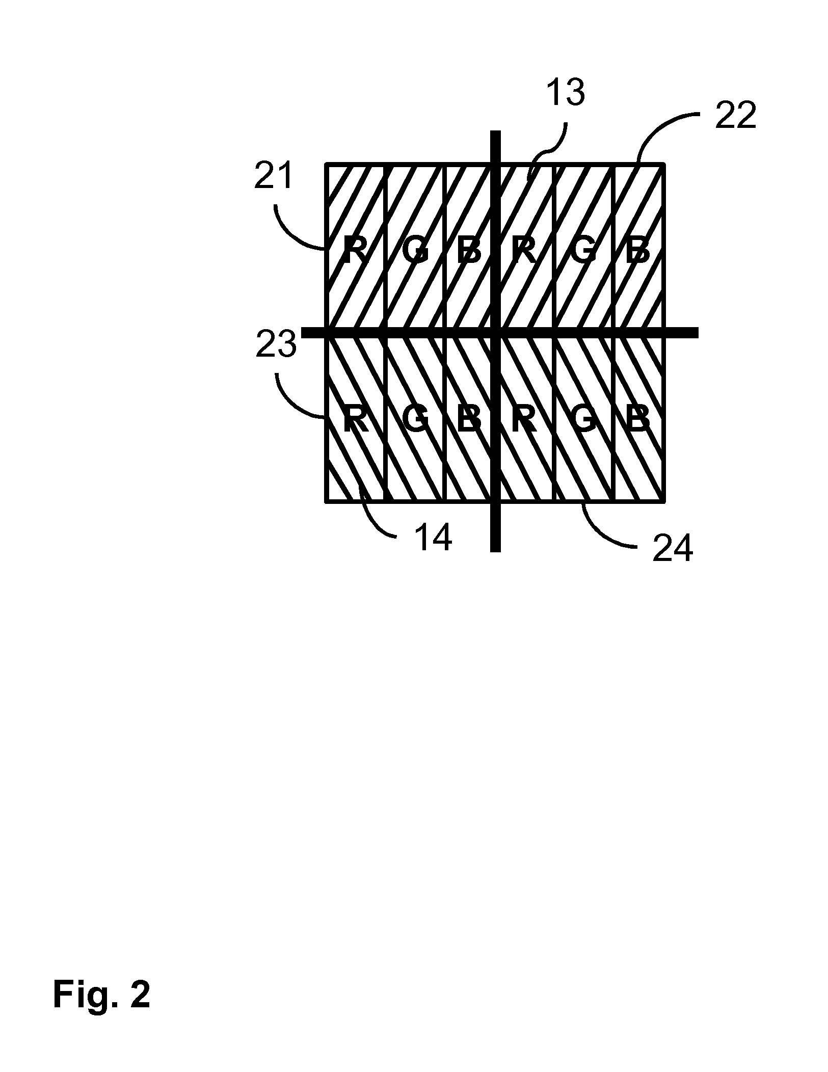
A pixel based 3D display (10) comprising a display panel (11), a striped polarizer (12) and a display controller (15). The display panel (11) comprises a plurality of pixels (41, 42) arranged in rows and columns, each pixel (41, 42) comprising at least four sub-pixels having different colors, the sub-pixels being arranged in two sub-rows and at least two sub-columns, the arrangement of the two sub-rows of two adjacent pixels in the same row being interchanged. The striped polarizer (12) overlays the display panel (11) and comprises stripes (13, 14) of transparent polarizing material, the stripes (13, 14) being arranged in an alternating pattern of left eye stripes (13) and right eye stripes (14), wherein the left eye stripes (13) are arranged for converting light to a first polarization and are overlaying one sub-row of the two sub-rows and wherein the right eye stripes (14) are arranged for converting light to a different second polarization and are overlaying the other sub-row of the two sub-rows. The display controller (15) is arranged for using sub-pixel rendering for controlling a light output of the pixels in accordance with a 3D image to be displayed.

Description

FIELD OF THE INVENTION[0001]This invention relates to a pixel based 3D display comprising a display panel, a striped polarizer and a display controller. The display panel comprising a plurality of pixels arranged in rows and columns, each pixel comprising sub-pixels having different colors. The striped polarizer overlays the display panel and comprises stripes of transparent polarizing material, the stripes being arranged in an alternating pattern of left eye stripes and right eye stripes, wherein the left eye stripes are arranged for converting light to a first polarization and the right eye stripes are arranged for converting light to a different second polarization. The display controller controls a light output of the pixels in accordance with a 3D image to be displayed.BACKGROUND OF THE INVENTION[0002]In most color displays, a pixel consists of three sub-pixels, a red one, a blue one and a green one. In short, this color combination is called RGB. With these three colors, the d...

Claims


Application Information

Patent Timeline
IPC IPC(8): G09G5/10G02B30/25
CPCG09G5/10H04N13/337H04N13/324H04N13/359G02B30/25
Inventor LANGENDIJK, ERNO HERMANUS
Owner KONINKLIJKE PHILIPS ELECTRONICS NV
Learn More