
Interference measurement method and apparatus for use in distributed antenna system

a technology of interference measurement and antenna system, applied in the direction of frequency-division multiplex, transmission monitoring, site diversity, etc., can solve the problems of not being able to apply unique scrambling crss, unable to measure the intra-cell interference of other antenna groups of the same cell, and unable to apply one pattern partially

Active Publication Date: 2014-03-27
SAMSUNG ELECTRONICS CO LTD
View PDF9 Cites 53 Cited by
  • Summary
  • Abstract
  • Description
  • Claims
  • Application Information

AI Technical Summary

Benefits of technology

This patent is about a way to measure interference in a DAS system to make communication more efficient. The technical effect of this invention is to help improve the quality and reliability of communication in the DAS system.

Problems solved by technology

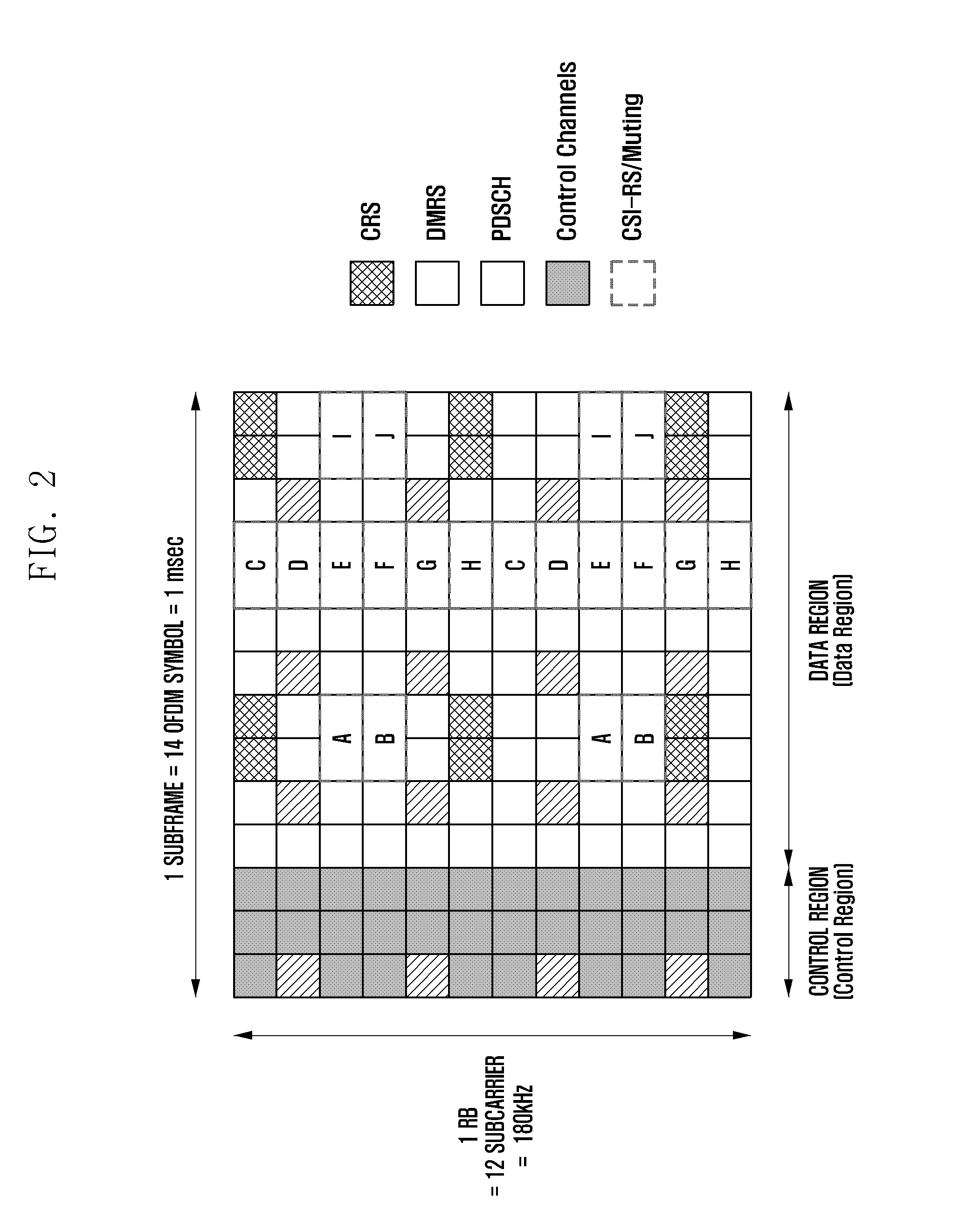
That is, although the muting may be applied to plural patterns, if the muting positions mismatch CSI-RS positions, it cannot be applied to one pattern partially.
The downlink interference includes the interference caused by the antennas of neighbor eNBs and thermal noise that are important in determining the downlink channel condition.
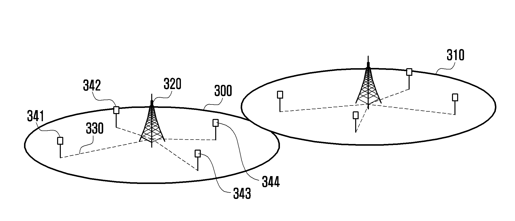
In the DAS-based LTE / LTE-A system, however, all antenna groups of the same cell transmit the CRS at the same timing and cannot apply unique scrambling CRSs.
If the different antenna groups of the same cell cannot transmit unique CRSs, although the inter-cell interference amount from the antenna groups of the neighbor eNBs can be measured, it is impossible to measure the intra-cell interference from other antenna groups of the same cell.
In the case of measuring the interference amount using the method described with reference to FIG. 5, the UE is capable of calculating the interference caused by the antenna groups of other cells but not the interference caused by the other antenna groups of the same cell, resulting in inaccurate Signal-to-Interference ratio.
The inaccurate Signal-to-Interference ratio causes significant performance degradation of the LTE / LTE-A system which determines downlink data rate using AMC based on the Signal-to-Interference ratio.

Method used


Image

  • Interference measurement method and apparatus for use in distributed antenna system
  • Interference measurement method and apparatus for use in distributed antenna system
  • Interference measurement method and apparatus for use in distributed antenna system

Examples


embodiment 1

[0101]If the conditions 1 and 2 are fulfilled, the UE skips interference measurement at the corresponding subframe. That is, if the IMR-based interference measurement and PDSCH reception occur at the same subframe, the UE generates the channel state information based on the previously measured interference without interference measurement at the corresponding subframe. At this time, the most recently measured interference may be used.

embodiment 2

[0102]If the conditions 1 and 2 are fulfilled, the UE skips interference measurement in the RBs carrying PDSCH addressed to itself in the corresponding subframe but measures interference in the RBs carrying no PDSCH to generate the channel state information. Such an example is shown in FIG. 11.

[0103]FIG. 11 is a diagram illustrating a principle of interference measurement method according to an embodiment of the present disclosure. In the embodiment, the interference measurement is skipped in the RB carrying PDSCH and performed in the RBs carrying no PDSCH.

[0104]Referring to FIG. 11, the UE receives PDSCH on the subband 0 but not on subband 1. Accordingly, the UE skips interference measurement on the subband 0 but performs interference measurement on the subband 1. At this time, the channel state information on the subband 0 is generated using the interference measured at the previous subframe on the subband 0 or the interference measured at the current subframe on the subframe 1. I...

embodiment 3

[0105]If the conditions 1 and 2 are fulfilled, the UE may process the interference measured in the RB carrying PDSCH addressed to the UE and the interference measured in the RB carrying no PDSCH at the corresponding subframe separately. As described above, if the UE measures the PDSCH as interference, excessive interference may be measured. By taking notice of this, the UE may compensate the interference measured in the RB carrying PDSCH to drop down at a predetermined rate. That is, the UE applies a constant Interference Adjustment Factor (IAF) to the interference measured in the RB carrying PDSCH. The IAF is multiplied to the interference measured in the RB carrying PDSCH to adjust the interference. The IAF may be notified to the UE through higher layer signaling or determined according to other control information configured at the UE. One approach for the UE to determine IAF according to other control information is to differentiate the value of IAF depending on the rank of PDSC...


PUM


Abstract

An interference measurement method and apparatus for use in a Distributed Antenna System (DAS) is provided. The method for transmitting channel state information based on interference measurement of a terminal in a Distributed Antenna System (DAS) according to the present disclosure includes receiving configuration of Interference Measurement Resource (IMR) for measuring interferences caused by plural Transmission Points (TPs), receiving control information including scheduling information on Physical Downlink Shared Channel (PDSCH), determining whether IMR-based interference measurement and PDSCH reception occur at a same subframe, and transmitting the channel state information generated according to a result of the determination. The interference measurement method and apparatus of the present disclosure is capable of measuring interference for efficient communication in the distributed antenna system.

Description

PRIORITY[0001]This application claims priority under 35 U.S.C. §119(a) to Korean Application Serial No. 10-2012-0106745, which was filed in the Korean Intellectual Property Office on Sep. 25, 2012 the entire content of which is incorporated herein by reference.BACKGROUND OF THE INVENTION[0002]1. Field of the Invention[0003]The present disclosure relates to an interference measurement method and apparatus for use in a Distributed Antenna System (DAS).[0004]2. Description of the Related Art[0005]The mobile communication system has evolved into a high-speed, high-quality wireless packet data communication system to provide data and multimedia services beyond the early voice-oriented services. Recently, various mobile communication standards, such as High Speed Downlink Packet Access (HSDPA), High Speed Uplink Packet Access (HSUPA), Long Term Evolution (LTE), and LTE-Advanced (LTE-A) defined in 3rd Generation Partnership Project (3GPP), High Rate Packet Data (HRPD) defined in 3rd Genera...

Claims


Application Information

Patent Timeline
IPC IPC(8): H04W24/10
CPCH04W24/10H04W72/54H04B17/345H04L5/0048H04L5/0062H04L5/0073H04B7/024H04B7/0626H04W72/541H04W72/542H04W24/08H04W72/232
Inventor KIM, YOUNSUNLEE, HYOJINKIM, YOUNGBUMCHO, JOONYOUNGJI, HYOUNGJU
Owner SAMSUNG ELECTRONICS CO LTD
Learn More