
Minimally invasive spine surgery instruments: spinal rod with flange

a spine surgery and minimally invasive technology, applied in the field of spine surgery instruments, can solve the problems of unnecessarily selecting the rod size, affecting the surgeon's ability to perform surgery, so as to achieve adequate engagement and improve the effect of assessing and controlling the proper alignmen

Inactive Publication Date: 2014-03-27
ATLAS SPINE
View PDF37 Cites 6 Cited by
  • Summary
  • Abstract
  • Description
  • Claims
  • Application Information

AI Technical Summary

Benefits of technology

The invention disclosed is a spinal rod with at least one flange, which solves the problems faced with current spinal rods. These rods are made in multiple lengths to accommodate patients with different needs, but often the view is obstructed and proper alignment is difficult to assess and control. The flanges on the spinal rod allow for better engagement with the receiving components, preventing discomfort and complications for the patient. Overall, this invention provides a more efficient and effective solution for minimally invasive spine surgery.

Problems solved by technology

When placed in placing the rods into the receiving components often the view is obstructed by tissue in the wound and proper alignment is difficult to assess and control.
It is common that a surgeon will select a rod size unnecessarily long to ensure a margin of error and adequate engagement.
The extra length can cause discomfort to the patient as well as other complications both intra and post operatively.
If a rod is too short for the construct length, loosening can occur over time leading to disassembly of the construct and result in the need for reoperation.

Method used


Image

  • Minimally invasive spine surgery instruments: spinal rod with flange
  • Minimally invasive spine surgery instruments: spinal rod with flange
  • Minimally invasive spine surgery instruments: spinal rod with flange

Examples


Embodiment Construction

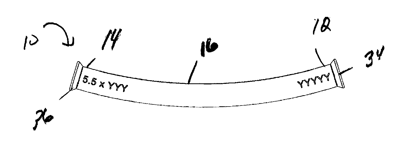
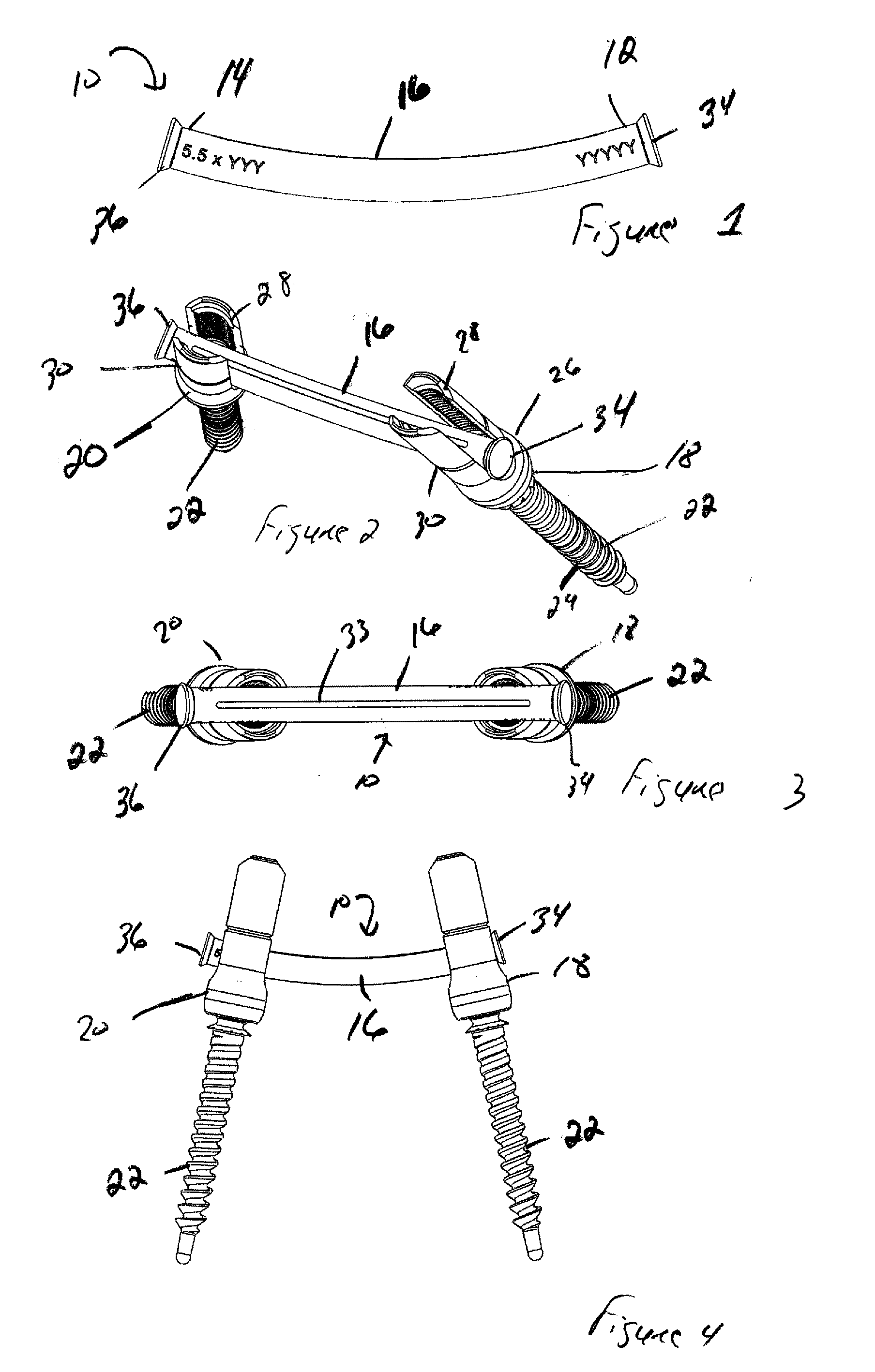
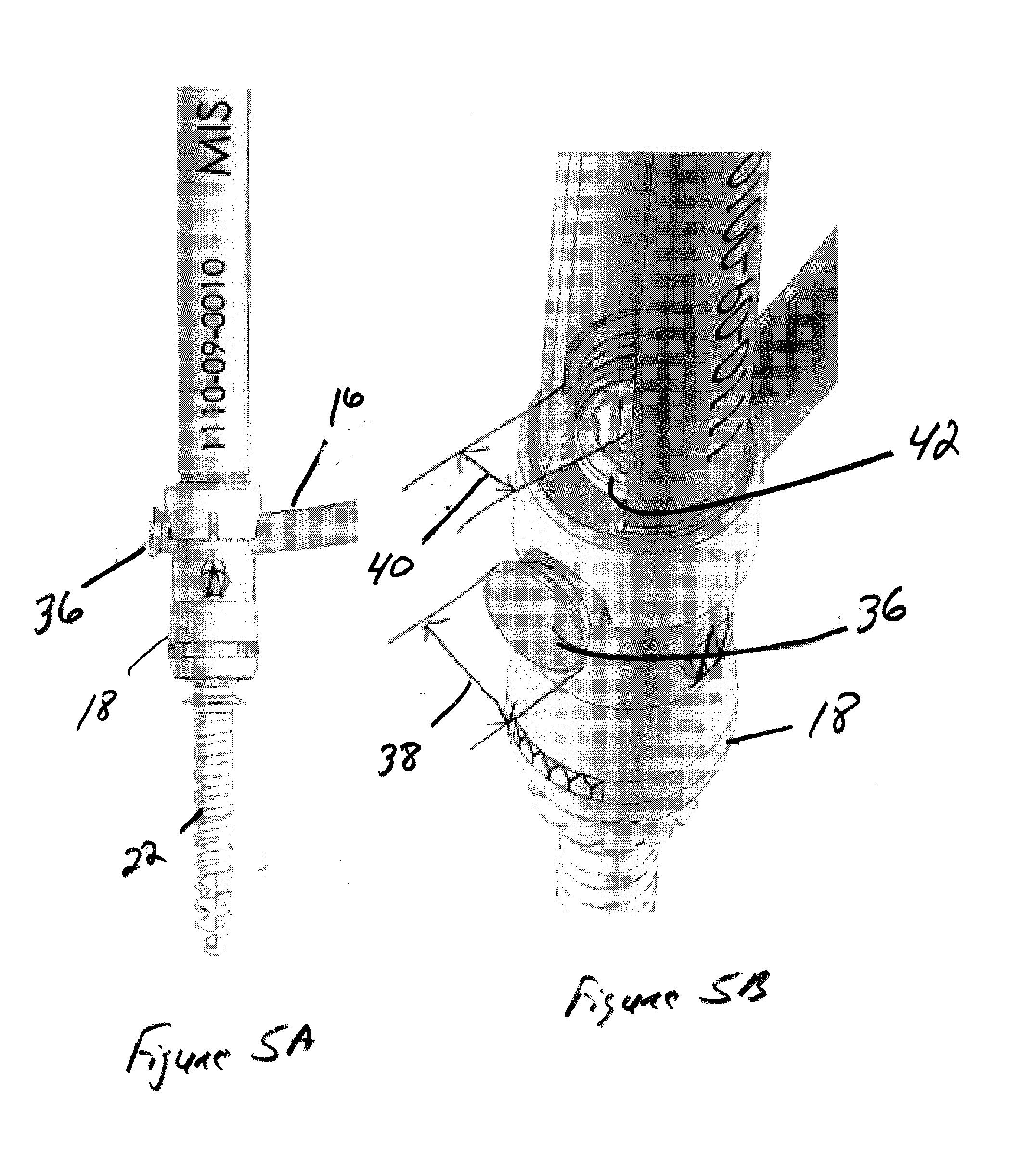
[0019]Referring to FIGS. 1-5B, set forth is a bone fixation device, illustrated herein as a spinal rod 10. The spinal rod 10 comprises a first end 12, a second opposing end 14, and a main body 16 there between. The main body 16 is preferably elongated having a generally cylindrical shape constructed and arranged to secure to a plurality of bone screw anchors, such as pedicle screw assemblies 18 and 20. In one embodiment, the main body 16 may be linear. Alternatively, the main body 16 may have a predetermined curvature. As used herein, the term pedicle screw assembly is used to define and / or describe commonly used orthopedic or spinal surgical instrumentation. While many embodiments of a pedicle screw exist commercially, the typical pedicle screw assembly consists generally of the pedicle screw 22 containing a threaded portion 24 which is inserted into a bone or spinal vertebrae. Connected to the screw is a housing unit 26 having upwardly shaped arms 28 and 30 which form a U-shape un...


PUM


Abstract

The present invention provides for a bone fixation device, illustrated as a spinal rod, for use in bone fixation surgeries. The bone spinal rod of the present invention is constructed and arranged to allow a surgeon to control proper placement while prohibiting the rod from passing out of a receiving component. In an illustrative embodiment, the spinal rod includes comprises a first end, a second opposing end, and a main body there between. At least one end contains a flange.

Description

CROSS REFERENCE TO RELATED APPLICATION[0001]In accordance with 37 C.F.R. 1.76, a claim of priority is included in an Application Data Sheet filed concurrently herewith. Accordingly, the present invention claims priority to U.S. Provisional Patent Application No. 61 / 704,132, entitled “MINIMALLY INVASIVE SPINE SURGERY INSTRUMENTS”, filed Sep. 21, 2012. The contents of which the above referenced application is incorporated herein by reference.FIELD OF THE INVENTION[0002]This invention relates to instruments and implants used to treat various problems of the spine; to a spinal rod for use in surgical procedures of the spine; and more particularly to a spinal rod with a t least one flange attached thereto.DESCRIPTION OF THE PRIOR ART[0003]Minimally invasive spine surgery can be use to effectively treat disorders of the spinal discs with minimal muscle related injury. In many procedures, a surgeon makes several small incisions (percutaneous) wherein a miniature camera (usually a laparosco...

Claims


Application Information

Patent Timeline
IPC IPC(8): A61B17/70
CPCA61B17/7002A61B17/7004A61B17/7083A61B17/8861
Inventor BAYNHAM, MATTHEW G.
Owner ATLAS SPINE
Learn More