Lane tracking apparatus and method using camera direction control

Active Publication Date: 2014-03-27
ELECTRONICS & TELECOMM RES INST
View PDF7 Cites 15 Cited by
  • Summary
  • Abstract
  • Description
  • Claims
  • Application Information

AI Technical Summary

Benefits of technology

[0012]Another object of the present invention is to more accurately obtain lane information from a curved road and track the lane by controlling the direction angle of a camera so that, as the curvature of a road increases, the direction angle of the camera is set to a larger angle.
[0013]A further object of the present invention is to more accurately obtain lane information from a curved road and track the lane by controlling

Problems solved by technology

This may cause a dangerous situation in which the direction angle of the camera is fixed at a direction identical to the travel direction of the vehicle, and so it is difficult to accurately capture an image of a lane in certain environments, such as a region containing curved roads, thus making it impossible to recognize the lane and to provide a warning to prevent a driver from straying outside a lane.
In lane tracking technology, it is very important to accurately capture an image of a lane, but, as described above, a tracking apparatus that is generally used is problematic in that the direction angle of a camera is fixed, and so it is impossible to accurately capture an image of a lane on a curved road.
Actually, it has been verified

Method used


Image

  • Lane tracking apparatus and method using camera direction control
  • Lane tracking apparatus and method using camera direction control
  • Lane tracking apparatus and method using camera direction control

Examples


Embodiment Construction

[0040]The present invention will be described in detail below with reference to the accompanying drawings. In the following description, redundant descriptions and detailed descriptions of known functions and elements that may unnecessarily make the gist of the present invention obscure will be omitted. Embodiments of the present invention are provided to fully describe the present invention to those having ordinary knowledge in the art to which the present invention pertains. Accordingly, in the drawings, the shapes and sizes of elements may be exaggerated for the sake of clearer description.

[0041]Hereinafter, preferred embodiments of the present invention will be described in detail with reference to the attached drawings.

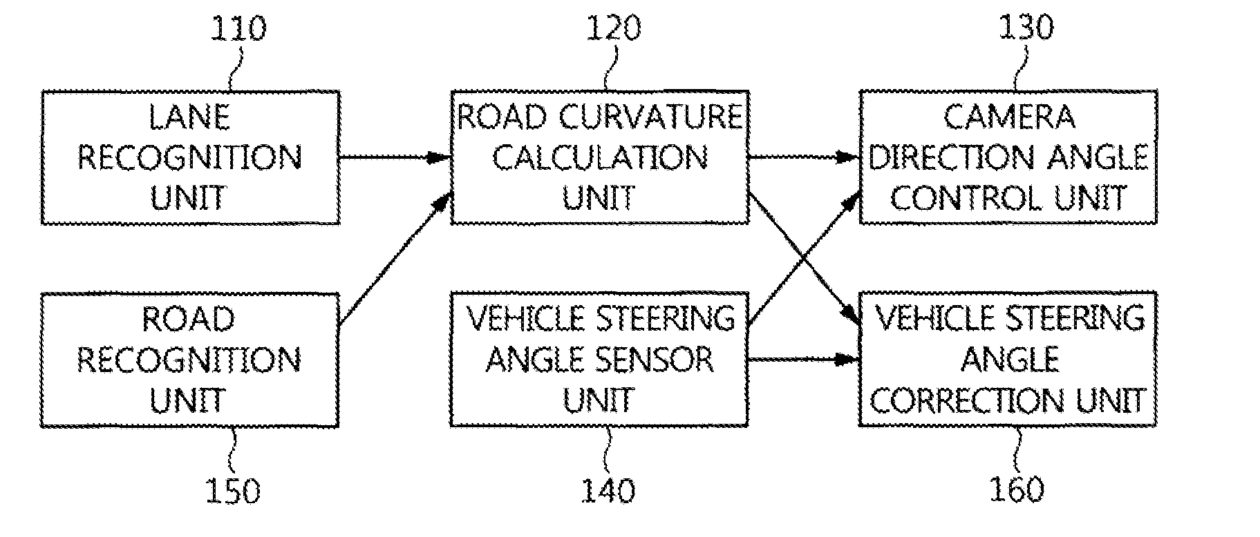
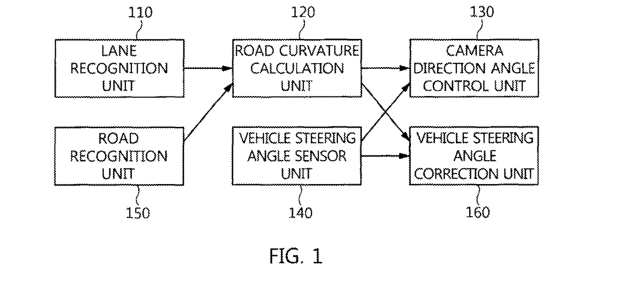
[0042]FIG. 1 is a block diagram showing a lane tracking apparatus using camera direction control according to an embodiment of the present invention.

[0043]Referring to FIG. 1, the lane tracking apparatus using camera direction control according to an embodiment o...


PUM


Abstract

A lane tracking apparatus and method using camera direction control is provided. The lane tracking apparatus using camera direction control includes a lane recognition unit for obtaining lane information from an image captured and acquired by a camera. A road curvature calculation unit calculates a curvature of a road using the lane information. A camera direction angle control unit controls a direction angle of the camera in consideration of the road curvature.

Description

CROSS REFERENCE TO RELATED APPLICATIONS[0001]This application claims the benefit of Korean Patent Application No. 10-2012-0107729, filed on Sep. 27, 2012, which is hereby incorporated by reference in its entirety into this application.BACKGROUND OF THE INVENTION[0002]1. Technical Field[0003]The present invention relates generally to a lane tracking apparatus using camera direction control and, more particularly, to a lane tracking apparatus and method using camera direction control, which can control the direction angle of a camera in consideration of the curvature of a road calculated by recognizing a lane.[0004]2. Description of the Related Art[0005]Recently, as various functionalities of vehicles have been improved, a variety of technologies for enhancing the safety and convenience of a driver and a passenger have been presented. In particular, lane tracking technology for safely maintaining a vehicle within a lane has been commercialized.[0006]In general, in lane tracking techno...

Claims


Application Information

Patent Timeline
IPC IPC(8): B60R1/00B62D6/00
CPCB62D6/00B60R1/00B62D15/025B60W30/12B60W40/06G01C21/30B60W2420/42B60W2540/18B60Y2300/12G06V20/588G08G1/167B60G2401/142G05D1/0246B62D1/28B60W10/20B60W2710/20B60G2800/24B60W2510/20B60G2400/824B60G2400/41B60T2201/08B60T2201/089G06T2207/30256B60W2552/30
Inventor ROH, MYUNG-CHANBYUN, JAE-MINNA, KI-INKIM, SUNG-HOON
Owner ELECTRONICS & TELECOMM RES INST
Why Eureka
Try Eureka