Stator core, split core block, stator manufacturing method and rotary electric machine

a stator core and split core technology, applied in the direction of dynamo-electric machines, electrical apparatus, magnetic circuit shapes/forms/construction, etc., can solve the problem of increasing iron loss in the stator core, and achieve the effect of reducing iron loss

Inactive Publication Date: 2014-04-03
YASKAWA DENKI KK
View PDF0 Cites 5 Cited by
  • Summary
  • Abstract
  • Description
  • Claims
  • Application Information

AI Technical Summary

Benefits of technology

[0011]It is possible to reduce iron loss with the stator core, the split core block

Problems solved by technology

In the configuration disclosed in Japanese Patent Application Publication No. 2006-311738, however

Method used


Image

  • Stator core, split core block, stator manufacturing method and rotary electric machine
  • Stator core, split core block, stator manufacturing method and rotary electric machine
  • Stator core, split core block, stator manufacturing method and rotary electric machine

Examples


Embodiment Construction

[0026]Embodiments of a stator core, a split core block, a stator manufacturing method and a rotary electric machine disclosed herein will now be described in detail with reference to the accompanying drawings which form a part hereof. However, the present invention is not limited to the following embodiments.

Stator Core

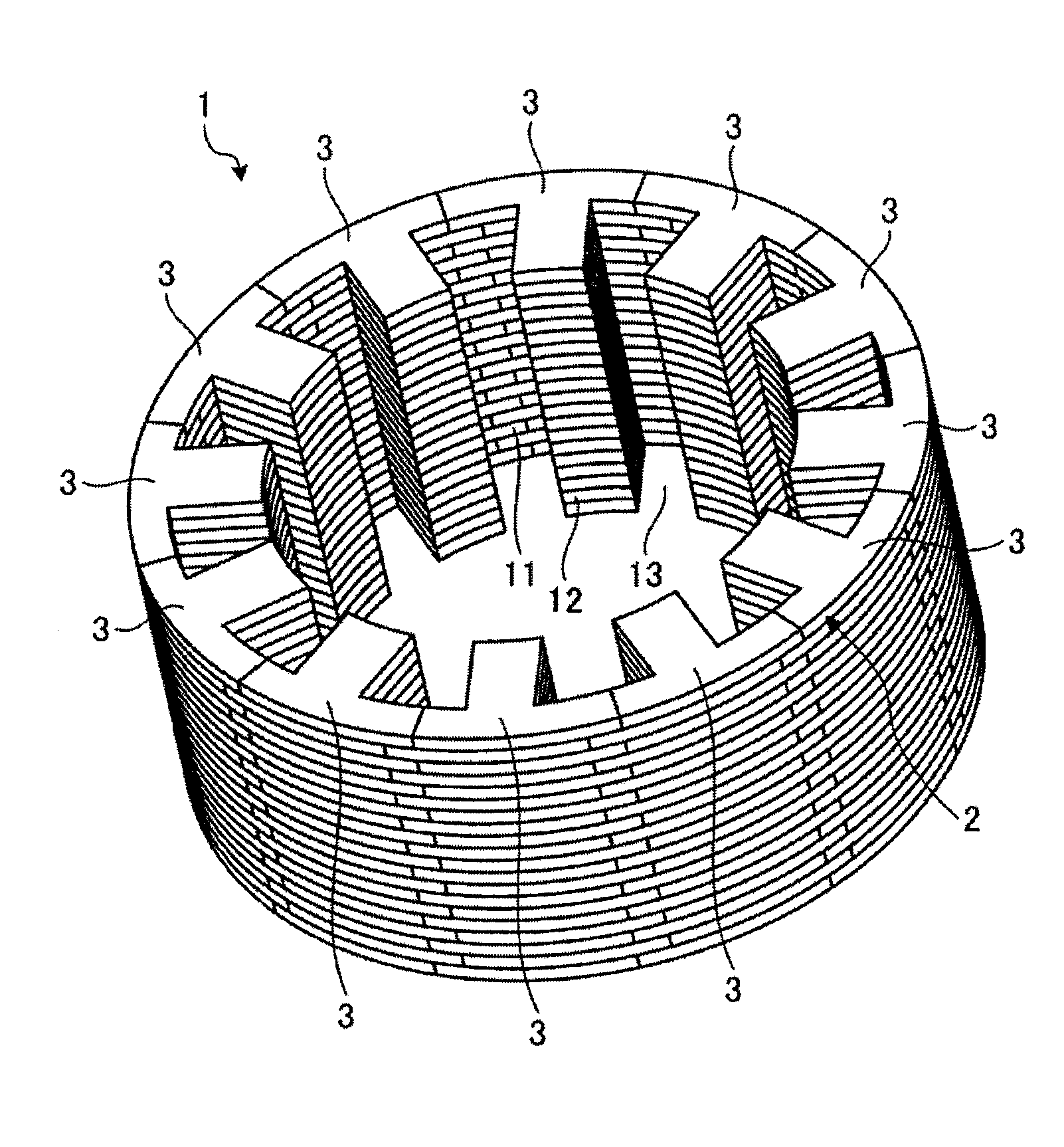
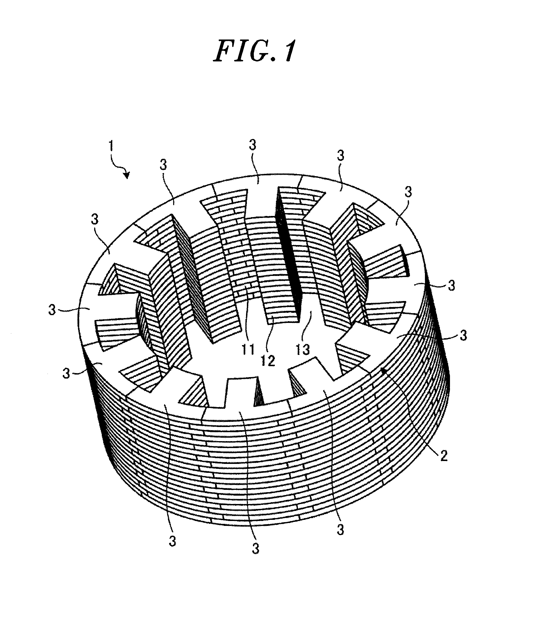
[0027]First, a stator core according to a preferred embodiment will be briefly described with reference to the accompanying drawings. FIG. 1 is a perspective view showing a stator core 1 according to a preferred embodiment.

[0028]The stator core 1 according to the present embodiment is used in, e.g., a motor 10 (see FIG. 11) to be described later. As shown in FIG. 1, the stator core 1 is formed by laminating a plurality of annular metal-made core plates 2 one on top of another. The number of the core plates 2 thus laminated can be appropriately set depending on the desired characteristics. As shown in FIG. 1, the stator core 1 formed by laminating the core plates 2 in...


PUM

PropertyMeasurementUnit
Lengthaaaaaaaaaa

Abstract

A stator core is formed by laminating a plurality of annular core plates one on top of another. The stator core includes a cylindrical yoke and a plurality of radially protruding teeth arranged at a specified interval along a circumferential direction of the yoke. Each of the core plates includes a plurality of annularly-arranged split cores each having a yoke portion forming the yoke and a tooth portion protruding from the yoke portion and forming the teeth. The yoke portion includes a first yoke section and a second yoke section extending different lengths at opposite lateral sides of the tooth portion.

Description

CROSS-REFERENCE TO RELATED APPLICATION[0001]The present disclosure contains subject matter related to that disclosed in Japanese Priority Patent Application No. 2012-217267 filed on Sep. 28, 2012. The contents of this application are incorporated herein by reference in their entirety.BACKGROUND OF THE INVENTION[0002]1. Field of the Invention[0003]Embodiments disclosed herein relate to a stator core, a split core block, a stator manufacturing method, and a rotary electric machine.[0004]2. Description of the Related Art[0005]There is conventionally available a stator core formed of a plurality of annular core plates laminated one on top of another. The stator core includes a cylindrical yoke and a plurality of teeth arranged at a specified interval along a circumferential direction of the yoke. The teeth protrude inward from the yoke.[0006]As the stator core of this laminated structure, there is known a stator core in which core plates are formed by interconnecting a plurality of spli...

Claims


Application Information

Patent Timeline
IPC IPC(8): H02K1/16H02K15/02
CPCH02K15/024H02K1/16H02K1/148Y10T29/49009
Inventor IRIE, KAZUAKI
Owner YASKAWA DENKI KK
Why Eureka
Try Eureka