Method And System For Fluid Flow Control In A Fluid Network System

a fluid network and fluid flow technology, applied in the field of fluid network systems, can solve the problems of large fluid network systems that in some applications consume substantial amounts of energy, substantial engineering effort to be commissioned, and complex process for determining the dynamic simulation model of the mine, so as to simplify the identification of network characteristics

Active Publication Date: 2014-04-03
ABB (SCHWEIZ) AG
View PDF27 Cites 100 Cited by
  • Summary
  • Abstract
  • Description
  • Claims
  • Application Information

AI Technical Summary

Benefits of technology

[0006]A general object of the present disclosure is to simplify the

Problems solved by technology

Large fluid network systems can in some applications consume substantial amounts of energy.
Attempts to use network models, i.e. models that describe fluid dynamical characteristics of the underground mine network, have been done but these suffer from sensitivity for changes in

Method used


Image

  • Method And System For Fluid Flow Control In A Fluid Network System
  • Method And System For Fluid Flow Control In A Fluid Network System
  • Method And System For Fluid Flow Control In A Fluid Network System

Examples


Embodiment Construction

[0043]In the following description, for purpose of explanation and not limitation, specific details are set forth, such as particular techniques and applications in order to provide a thorough understanding of the present disclosure. However, it will be apparent for a person skilled in the art that the present disclosure may be practiced in other embodiments that depart from these specific details. In other instances, detailed description of well-known methods and apparatuses are omitted so as not to obscure the description with unnecessary details.

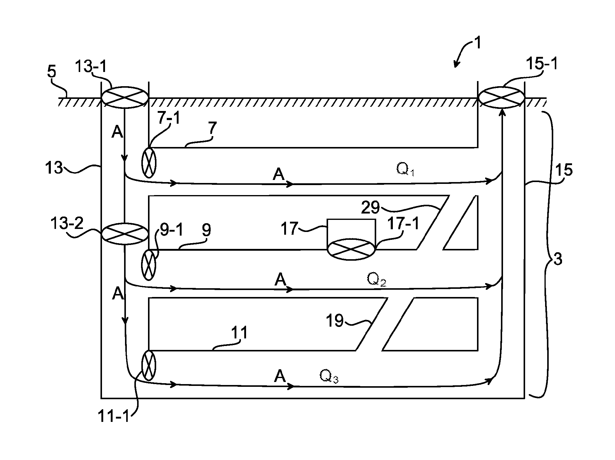
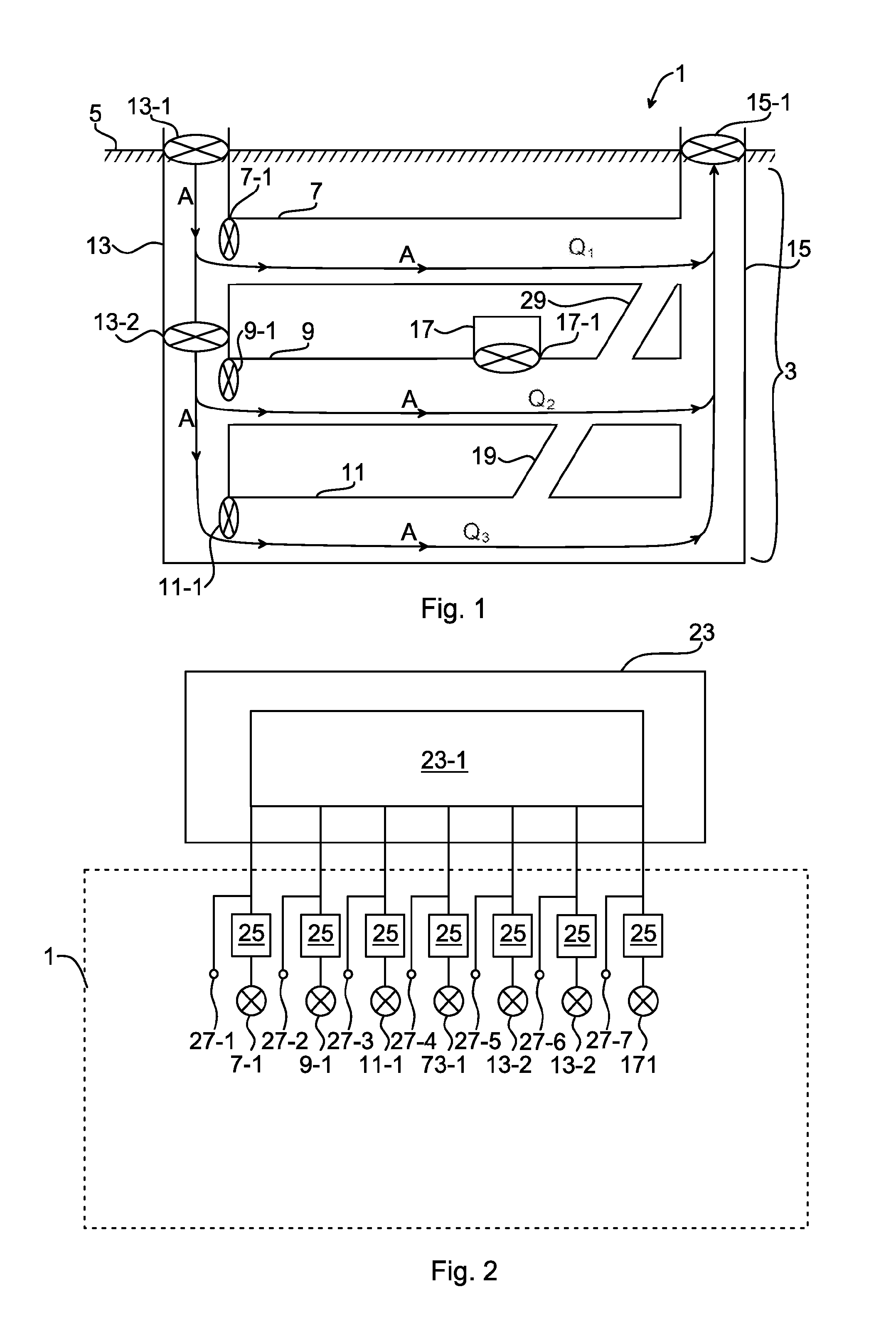
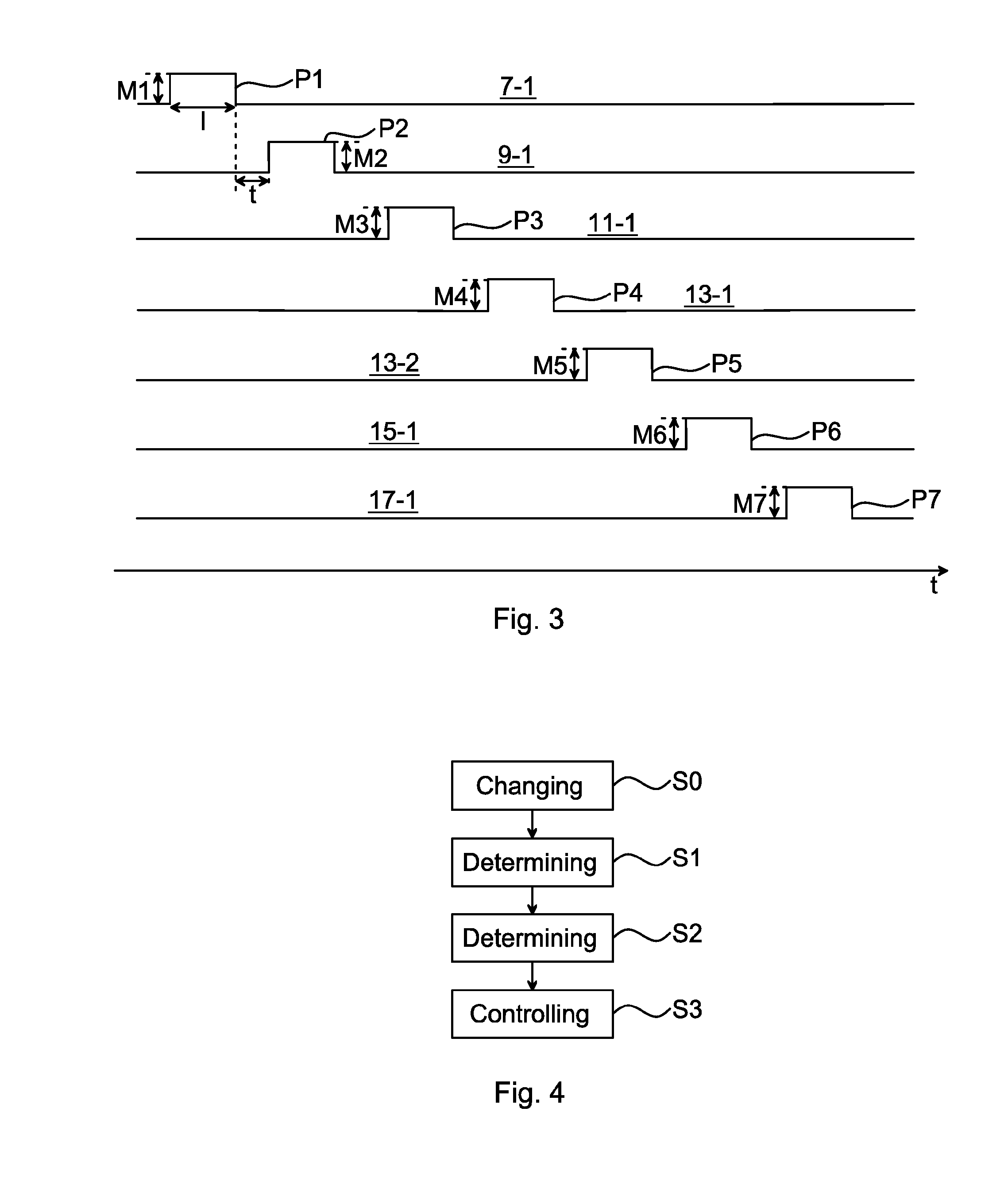
[0044]The present disclosure may be utilized for fluid flow control in a fluid network system such as a ventilation system of an underground mine, a building ventilation system, district heating / cooling, a drainage system for e.g. underground mines and similar systems, as would be apparent to the person skilled in the art. For illustrative purposes only, the fluid network system will in the following be exemplified by a ventilation system...


PUM


Abstract

A method of controlling fluid flow in a fluid network system by means of a plurality of fluid machines. The disclosure provides a simple empirical method of identifying network characteristics of the fluid network system used for providing the required fluid flow rate in the fluid network system utilizing minimal fluid machine power. The method includes the steps of determining a relation between a change in fluid machine speed and a corresponding change in fluid flow rate for each of the plurality of fluid machines empirically; determining a minimum total fluid machine power which provides a minimum required flow rate in the fluid network system based on a constraint involving the relation between the fluid flow rate and the corresponding fluid machine speed, and controlling a speed of the plurality of fluid machines such that the minimum total fluid machine power in the fluid network system is attained.

Description

FIELD OF THE INVENTION[0001]The present disclosure relates to fluid network systems and in particular to ventilation control in such systems.BACKGROUND OF THE INVENTION[0002]Large fluid network systems can in some applications consume substantial amounts of energy. An example of such a fluid network system is a ventilation system of an underground mine. Such a ventilation system can comprise a plurality of fans which need to be operated in order to maintain sufficient air quality for healthy working conditions in the mine.[0003]Ventilation on demand (VOD) control is sometimes utilized today to reduce the amount of consumed energy in underground mines. In short VOD means that fresh air is directed to specific locations in the underground mine only when needed and at sufficient amount to achieve a healthy working environment. Attempts to use network models, i.e. models that describe fluid dynamical characteristics of the underground mine network, have been done but these suffer from s...

Claims


Application Information

Patent Timeline
IPC IPC(8): E21F1/00G05D7/06E21F1/02
CPCE21F1/00G05D7/0617E21F1/02G05D7/0676G05D7/0682Y10T137/0318Y02B30/70
Inventor LUNDH, MICHAELNYQVIST, JAN
Owner ABB (SCHWEIZ) AG
Why Eureka
Try Eureka