Bundle division structure for flexible circuit cable

a flexible circuit and division structure technology, applied in the direction of cable junctions, transient suppressor details, high frequency circuit adaptations, etc., can solve the problems of signal transmission lines being severely restricted, difficult to flex and move, and electromagnetic interference among signal transmission lines, so as to reduce mutual interference, suppress electromagnetic interference, and reduce electrostatic discharge

Inactive Publication Date: 2014-04-10
ADVANCED FLEXIBLE CIRCUITS
View PDF4 Cites 15 Cited by
  • Summary
  • Abstract
  • Description
  • Claims
  • Application Information

AI Technical Summary

Benefits of technology

[0018]With the technical solution adopted by the present invention, during the interaction between a flexible circuit cable and a moving part, the bundle division unit functions to position and protect the conductor units so that the conductor units are not readily damaged due to rubbing in the interaction thereof with the moving part. Further, the conductor units are divided into groups and separately bundled to reduce mutual interference between different conductor groups that transmit different electrical signals.
[0019]Further, static electricity generated due to rubbing in the interaction with a moving part is conducted to the surrounding in order to reduce electrostatic discharge and suppress electromagnetic interference. Thus, during transmission of high frequency differential mode signals with an electronic device, errors and distortions of transmitted signals can be avoided.

Problems solved by technology

By bundling all the signal transmission lines in the same bundle, electromagnetic interference among the signal transmission lines may result.
Further, the known technology, when applied to bundle lines, often results in being excessively stiff, making it difficult to flex and move.
This subjects the signal transmission lines to a severe constrain and may even cause damage of the signal transmission lines.
It is thus appreciated that signal transmission lines that are bundled with the conventional ways are generally not fit for use in miniaturized hinge structures that are currently included in for example the fields of mobile phones, digital cameras, and notebook computers.
Further, in applications where a flexible circuit cable is subject to frequency bending and interference by adjacent moving parts around the flexible circuit cable, reliability of signal transmission is often affected by electrostatic discharge induced by machine operations.
Since the capability of a circuit cable to bear frequency bending and the number of bending that the circuit cable can take are of importance, the conventional arrangements of a circuit cable or wires and protection realized with an outer jacket, although being effective to extend through a bore of a hinge structure, may get readily damaged before the designated number of bending is reached due to stress concentration occurring at corners of the circuit cable caused by folding and rotating and abrasion of the circuit cable with the hinge structure resulting from rotation operations applied by a user during the use of a product including the circuit cable.
However, the circuit cable and wires and the protection structures thereof may contact and rub each other due to movement thereof caused by rotation operations and thus causing some of the wires to squeeze each other and get distorted and deformed, leading interruption of transmission conducted through the conductor wires and losing the desired function of transmission.
Further, the conventional way of bundling is quite labor-intense in assembling and is hard to meet the requirement for product standardization.

Method used


Image

  • Bundle division structure for flexible circuit cable
  • Bundle division structure for flexible circuit cable
  • Bundle division structure for flexible circuit cable

Examples


first embodiment

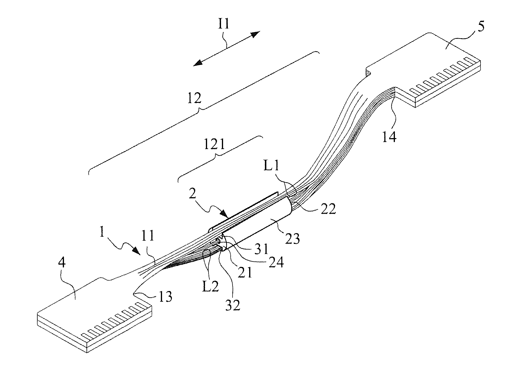
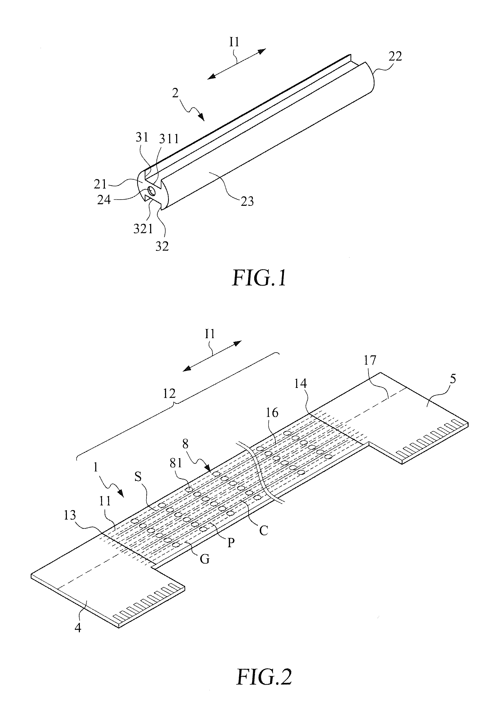
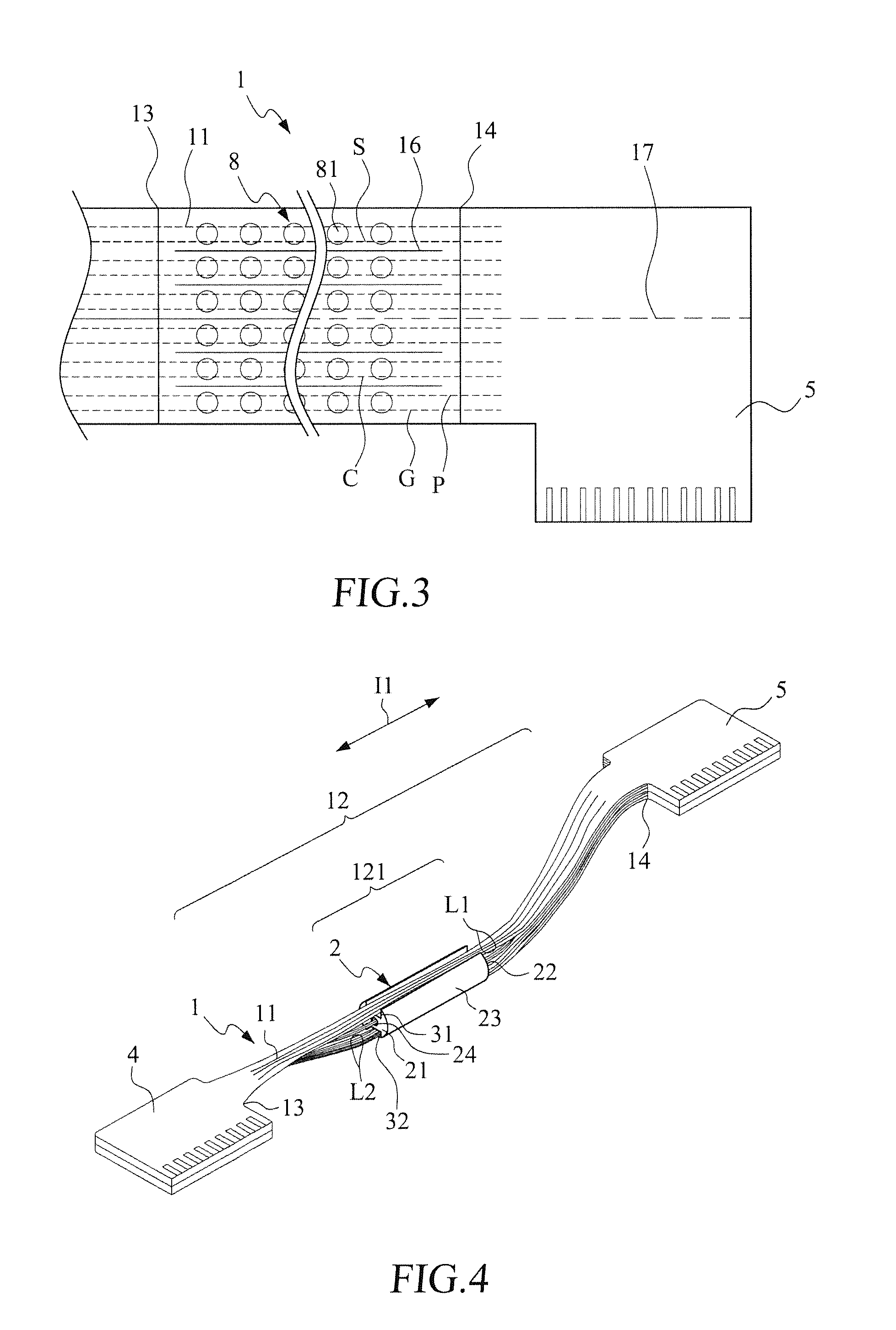
[0036]With reference to the drawings and in particular to FIGS. 1-4, FIG. 1 is a schematic view showing the structure of a bundle division structure for a flexible circuit cable according to the present invention; FIG. 2 is a schematic view showing the structure of a flexible circuit cable; FIG. 3 is a partial enlarged view of the flexible circuit cable; and FIG. 4 is a schematic view showing the structure of the present invention. As shown in the drawings, a flexible circuit cable 1 used in a bundle division structure according to the present invention comprises a plurality of conductor units 11, which extends in an extension direction I1 and is collected together to form a clustered structure 12. The clustered structure defines at least one bundle division section 121.

[0037]The bundle division structure comprises a bundle division unit 2, a first conductor unit receiving slot 31, and at least one second conductor unit receiving slot 32. The bundle division unit 2 comprises a first...

third embodiment

[0057]Referring to FIG. 15, a schematic view is given to show the structure of a third embodiment according to the present invention. As shown in the drawing, the bundle division structure for the flexible circuit cable according to the present invention further comprises at least one third conductor unit receiving slot 33 and at least one third conductor group L3.

[0058]The third conductor unit receiving slot 33 is spaced from the first conductor unit receiving slot 311. The third conductor unit receiving slot 33 has a bottom 331 lower than the outer circumferential surface 23 of the bundle division unit 2 by a height H and extends in the extension direction I1 from the first end 21 of the bundle division unit 2 to the second end 2.

[0059]The third conductor group L3 is received in the third conductor unit receiving slot 33 and extends from the first end 21 of the bundle division unit 2 through the third conductor unit receiving slot 33 to the second end 22 of the bundle division uni...


PUM


Abstract

Disclosed is a bundle division structure for a flexible circuit cable. The flexible circuit cable includes a plurality of conductor units that extends in an extension direction and is collected together to form a clustered structure. The clustered structure defines at least one bundle division section. The bundle division structure includes a bundle division unit, at least a pair of conductor unit receiving slots. The conductor units of the bundle division section are divided into groups that are respectively received in the conductor unit receiving slot. The bundle division unit is coupled to a protection member for protection and positioning purposes.

Description

BACKGROUND OF THE INVENTION[0001]1. Field of the Invention[0002]The present invention relates to a bundle division structure for a signal transmission cable, and in particular to a bundle division structure for a flexible circuit cable.[0003]2. The Related Arts[0004]Various electronic devices that are currently used require an increasing amount of data to be transmitted through signal lines so that the number of the signal lines used is increase and the frequency used to transmit signals is also raised. Thus, a differential mode of high frequency transmission is commonly adopted to suppress electromagnetic (EMI). For example, such a technology is widely used in USB or LVDS signals to suppress EMI.[0005]After the signal lines have been harnessed, it is a common practice to bundle the signal lines for positioning on the one hand and for protection on the other hand. The conventional way of bundling signal transmission lines is to bundle all the signal transmission lines together and t...

Claims


Application Information

Patent Timeline
Patent Type & Authority Applications(United States)
IPC IPC(8): H05K9/00
CPCH05K9/00H05K9/0066H05K1/148H05K2201/053H05K2201/2027H05K1/0253H05K1/028H05K2201/09063
Inventor SU, KUO-FU
Owner ADVANCED FLEXIBLE CIRCUITS
Why Eureka
Try Eureka