Approach for controlling operation of oil injectors

a technology for oil injectors and control valves, applied in the direction of programme-control, machines/engines, instruments, etc., can solve the problems of piston wear and piston slap

Active Publication Date: 2014-04-10
FORD GLOBAL TECH LLC
View PDF8 Cites 17 Cited by
  • Summary
  • Abstract
  • Description
  • Claims
  • Application Information

AI Technical Summary

Benefits of technology

[0001]Piston cooling jets or oil injectors may be implemented in an engine to provide engine cylinder cooling and lubrication. In particular, each oil injector sprays oil onto an underside of a corresponding piston to create a cooling effect o

Problems solved by technology

However, the inventors have recognized several potential issues with such an approach.
For example, since the oil injectors are not operated until the eng

Method used


Image

  • Approach for controlling operation of oil injectors
  • Approach for controlling operation of oil injectors
  • Approach for controlling operation of oil injectors

Examples


Embodiment Construction

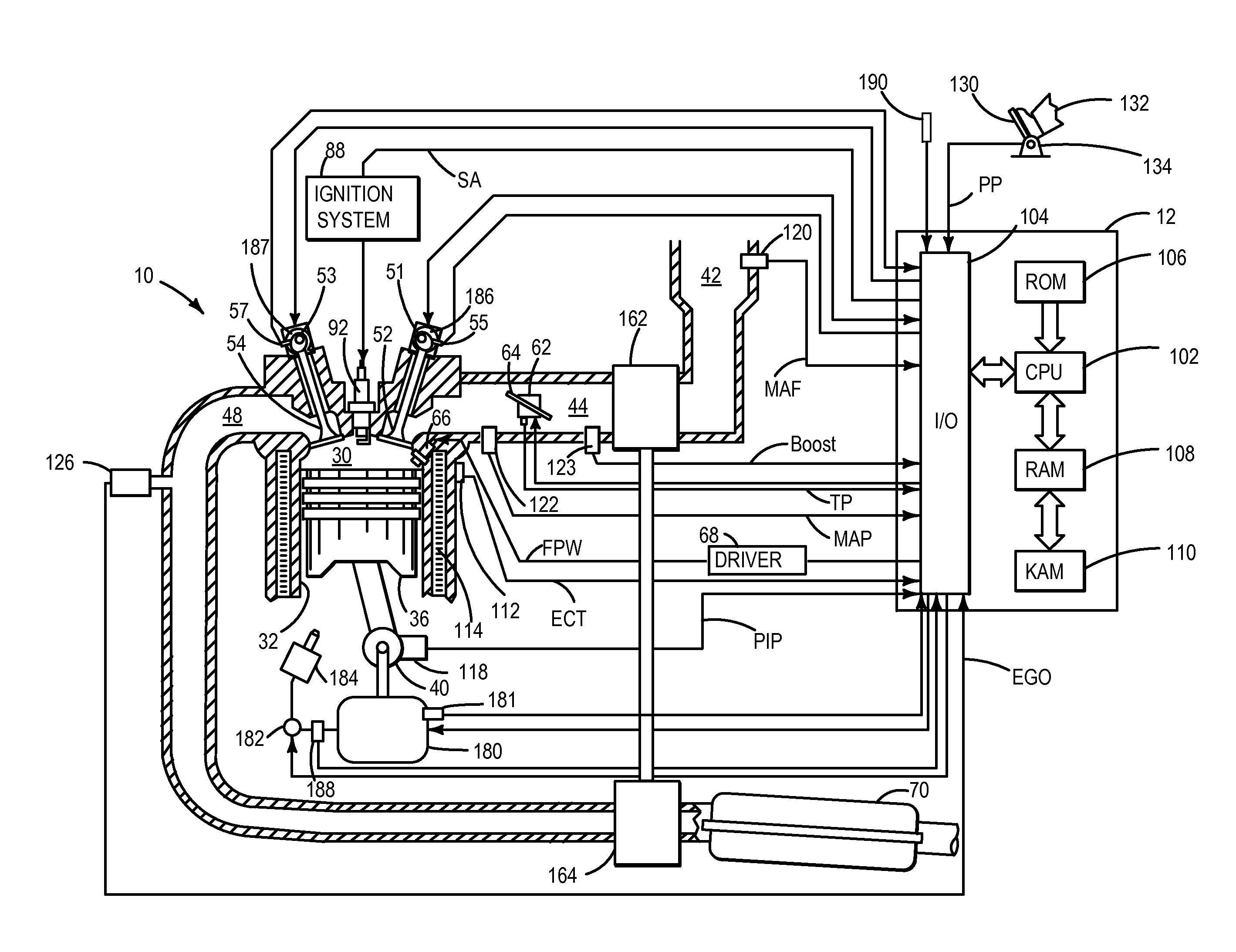
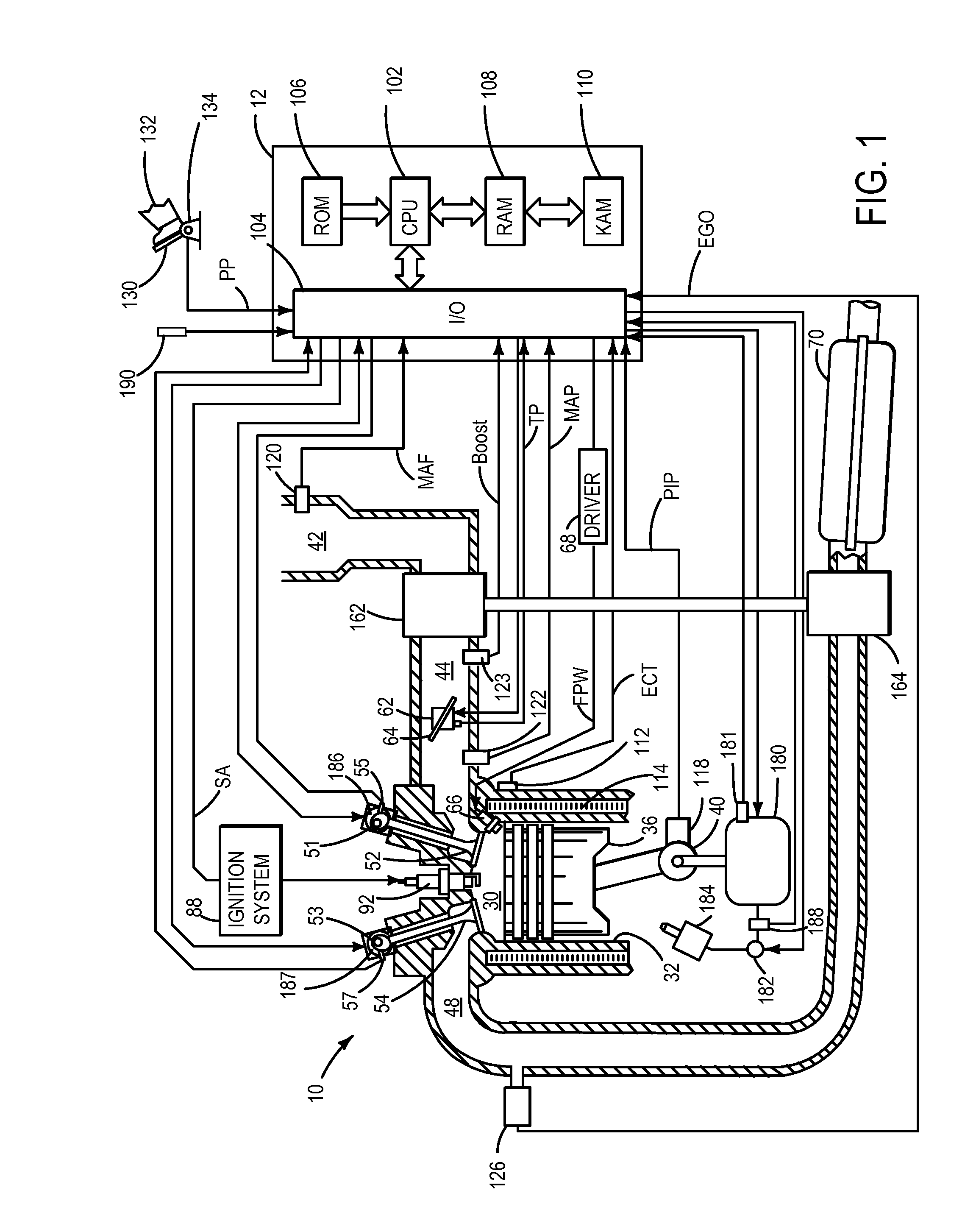
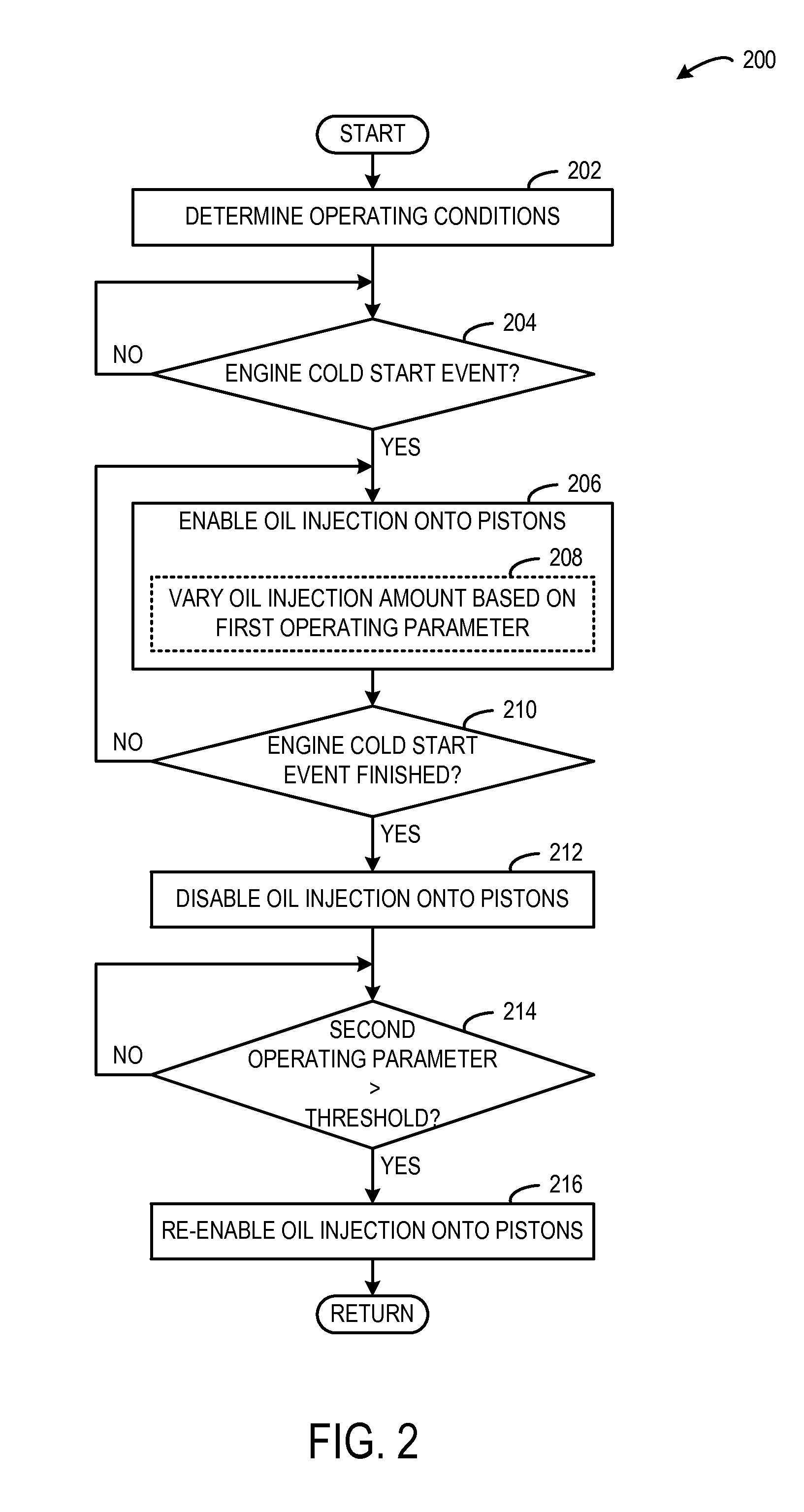
[0017]The present disclosure relates to controlling operation of oil injectors in an engine. More particularly, the present disclosure relates to controlling operation of oil injectors (e.g., on / off times) to provide lubrication and cooling when appropriate while also promoting engine heating after an engine cold start event. In one example, oil injector operation may be initially enabled during an engine cold start event to inject oil onto pistons of the engine to provide lubrication for a selected number of combustion events from rest, such as only once or twice per cylinder, for example. Then, operation of the oil injectors may be disabled to promote engine heating. In particular, continuous operation of the oil injectors may inhibit heating of the cylinder walls after the engine cold start event. Once the engine has reached a suitable operating temperature for stable combustion, operation of the oil injectors may be re-enabled to provide oil for piston cooling.

[0018]Furthermore,...


PUM


Abstract

Various embodiments of systems and methods related to controlling oil injection for piston cooling in an engine are disclosed. In one embodiment, a method includes during an engine cold start event, enabling oil injection onto a piston of an engine, disabling oil injection after the engine cold start event, and re-enabling oil injection after the engine cold start event based on a first operating parameter.

Description

BACKGROUND AND SUMMARY[0001]Piston cooling jets or oil injectors may be implemented in an engine to provide engine cylinder cooling and lubrication. In particular, each oil injector sprays oil onto an underside of a corresponding piston to create a cooling effect on the piston. Furthermore, the oil propagates from the underside of the piston to the surrounding walls of a corresponding engine cylinder as the piston reciprocates in the engine cylinder to provide a cooling effect to the combustion chamber.[0002]In one example, oil injector operation may be disabled at engine startup until the engine cylinders have reached an operating temperature that is suitable for stable combustion, at which point oil injector operation may be enabled. In this example, oil injector operation may be delayed to promote engine heating in order to reduce particulate matter generated as a result of incomplete combustion.[0003]However, the inventors have recognized several potential issues with such an ap...

Claims


Application Information

Patent Timeline
IPC IPC(8): F01M1/16F02D28/00
CPCF01M1/08F01L1/3442F01L2001/34423F01M1/16F01P3/08F01P2025/32F01P2025/40F01P2025/46F01P2037/02
Inventor MAKI, CLIFFORD E.CUNNINGHAM, RALPH WAYNEHANSHAW, JAMIE CHARLESBIDNER, DAVID
Owner FORD GLOBAL TECH LLC
Why Eureka
Try Eureka