Turbine blade fatigue life analysis using non-contact measurement and dynamical response reconstruction techniques

a technology of non-contact measurement and turbine blades, applied in the direction of instruments, force/torque/work measurement, data acquisition and logging, etc., can solve the problems of blade failure, life-cycle cost of a turbine system, and progressive and localized structural damage of fatigu

Active Publication Date: 2014-04-10
SIEMENS ENERGY INC
View PDF10 Cites 25 Cited by
  • Summary
  • Abstract
  • Description
  • Claims
  • Application Information

AI Technical Summary

Benefits of technology

[0012]According to an aspect of the invention, there is provided a method dynamically reconstructing a stress and strain field of a turbine blade, including providing a set of response measurements from at least one location on a turbine blade, band-pass filtering the set of response measurements based on an upper frequency limit and a lower frequency limit, determining an upper envelope and a lower envelope of the set of response measurements from local minima and local

Problems solved by technology

Fatigue is the progressive and localized structural damage that occurs when a material is subjected to cyclic loading.
Blade failure can be costly due to the fact that the failure of one blade can damage other blades and cause the downtime of an entire system; therefore, improving blade durability can help reduce life-cycle cost of a turbine system.
The traditional analysis might have a potential limitation of that the monitoring system can only monitor a few surface locations.
(1) The system and method can only measure a few points due to the hardware constraints. The stress or strain fields of the entire blade are difficult to infer.
(2) The stress and strain field analysis depe

Method used


Image

  • Turbine blade fatigue life analysis using non-contact measurement and dynamical response reconstruction techniques
  • Turbine blade fatigue life analysis using non-contact measurement and dynamical response reconstruction techniques
  • Turbine blade fatigue life analysis using non-contact measurement and dynamical response reconstruction techniques

Examples


Embodiment Construction

[0034]Exemplary embodiments of the invention as described herein generally provide systems and methods for dynamical response reconstruction. While embodiments are susceptible to various modifications and alternative forms, specific embodiments thereof are shown by way of example in the drawings and will herein be described in detail. It should be understood, however, that there is no intent to limit the invention to the particular forms disclosed, but on the contrary, the invention is to cover all modifications, equivalents, and alternatives falling within the spirit and scope of the invention.

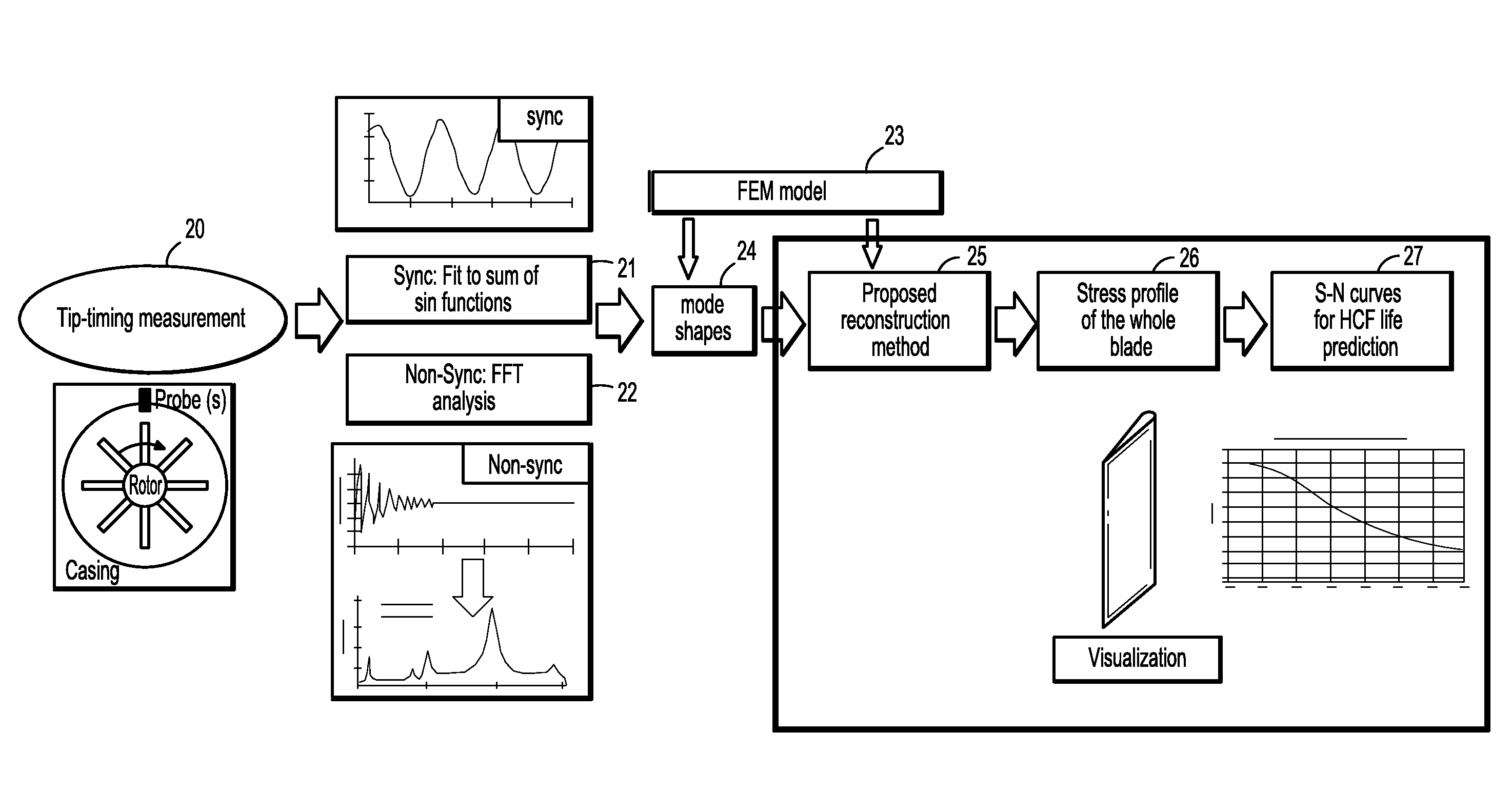
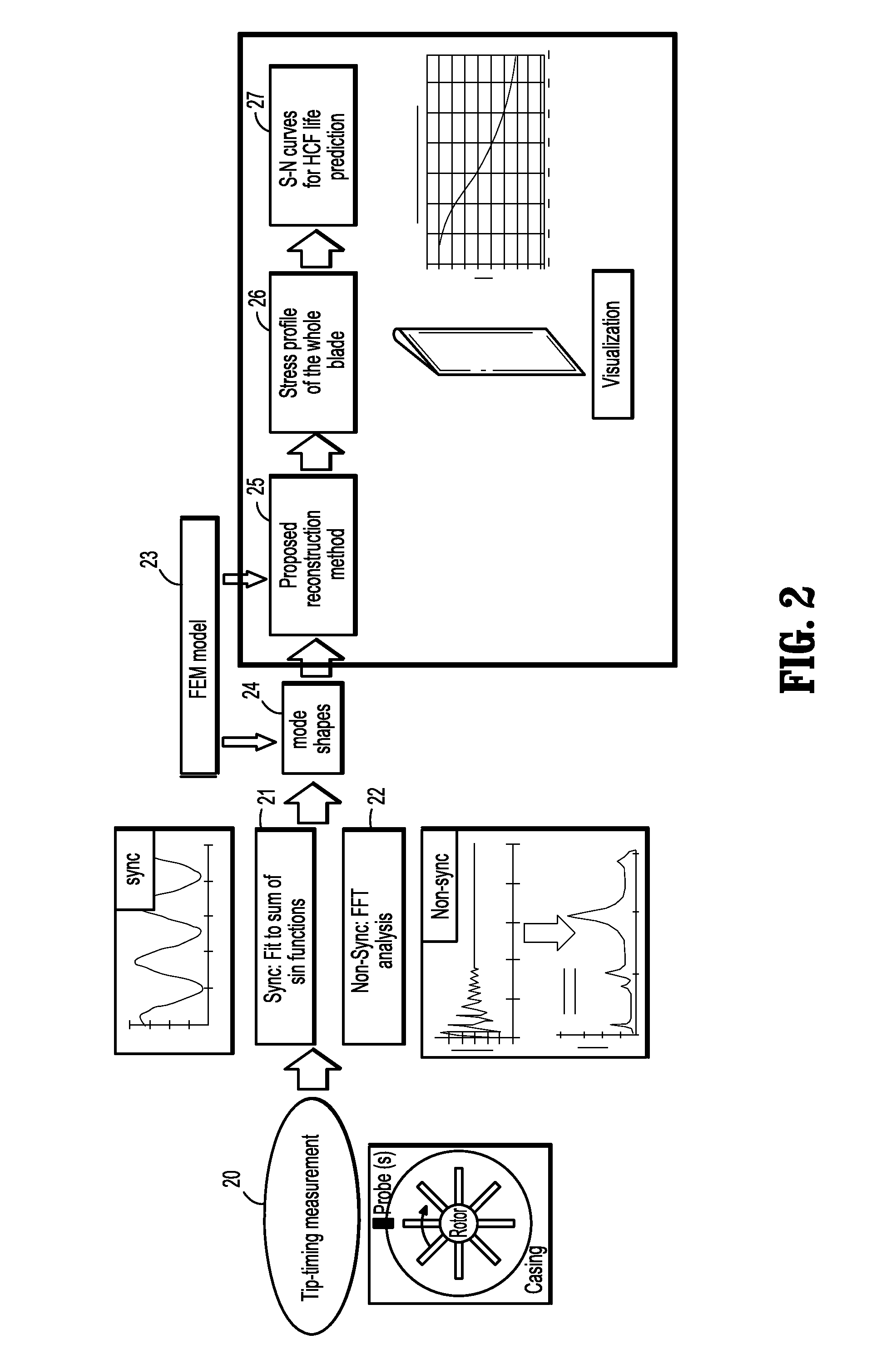
[0035]A system and method according to embodiments of the disclosure can address the drawbacks of conventional systems and methods by using dynamical response reconstruction methodologies. The basic idea is to reconstruct the stress and strain fields of the entire blade based on a finite element model, the measured responses and an empirical mode decomposition technique. A workflow of a syste...


PUM


Abstract

A method dynamically reconstructing a stress and strain field of a turbine blade includes providing a set of response measurements from at least one location on a turbine blade, band-pass filtering the set of response measurements based on an upper frequency limit and a lower frequency limit, determining an upper envelope and a lower envelope of the set of response measurements from local minima and local maxima of the set of response measurements, calculating a candidate intrinsic mode function (IMF) from the upper envelope and the lower envelope of the set of response measurements, providing an N×N mode shape matrix for the turbine blade, where N is the number of degrees of freedom of the turbine blade, when the candidate IMF is an actual IMF, and calculating a response for another location on the turbine blade from the actual IMF and mode shapes in the mode shape matrix.

Description

CROSS REFERENCE TO RELATED UNITED STATES APPLICATIONS[0001]This application claims priority from “System And Method For Turbine Blade Fatigue Life Analysis Using Non-Contact Measurement And Dynamical Response Reconstruction Techniques”, U.S. Provisional Application No. 61 / 710,179 of Guan, et al., filed Oct. 5, 2012, the contents of which are herein incorporated by reference in their entirety.TECHNICAL FIELD[0002]This application is directed to turbine blade fatigue life analysis using non-contact measurement and dynamical response reconstruction techniques.DISCUSSION OF THE RELATED ART[0003]Fatigue is the progressive and localized structural damage that occurs when a material is subjected to cyclic loading. Traditionally, most attention has focused on situations that require more than 104 cycles to failure where stress is low and deformation is primarily elastic, known as high-cycle fatigue situations. In these situations, material performance is commonly characterized by an S-N cur...

Claims


Application Information

Patent Timeline
IPC IPC(8): G01L5/00
CPCG01L5/00G01M5/0016G01M5/0041G01M15/14G06F17/40G16Z99/00G01D21/00G01H17/00G01N3/56
Inventor GUAN, XUEFEIZHANG, JINGDANZHOU, SHAOHUA KEVINULERICH, NANCY H.KIM, NAM EUNGTEVS, NIKOLAI R.
Owner SIEMENS ENERGY INC
Why Eureka
Try Eureka