
Method for controlling a turbocharger arrangement with an electric actuator and spring

a technology of electric actuator and turbocharger, which is applied in the direction of engine controller, combustion engine, machine/engine, etc., can solve the problems of limited engine downsizing, insufficient boost to be delivered to the engine, and engine may not supply the desired torque and output, etc., to improve the torque/power output density of the engine, increase the pressure in the intake manifold, and increase the flow of air into the engine

Active Publication Date: 2014-04-17
FORD GLOBAL TECH LLC
View PDF18 Cites 14 Cited by
  • Summary
  • Abstract
  • Description
  • Claims
  • Application Information

AI Technical Summary

Benefits of technology

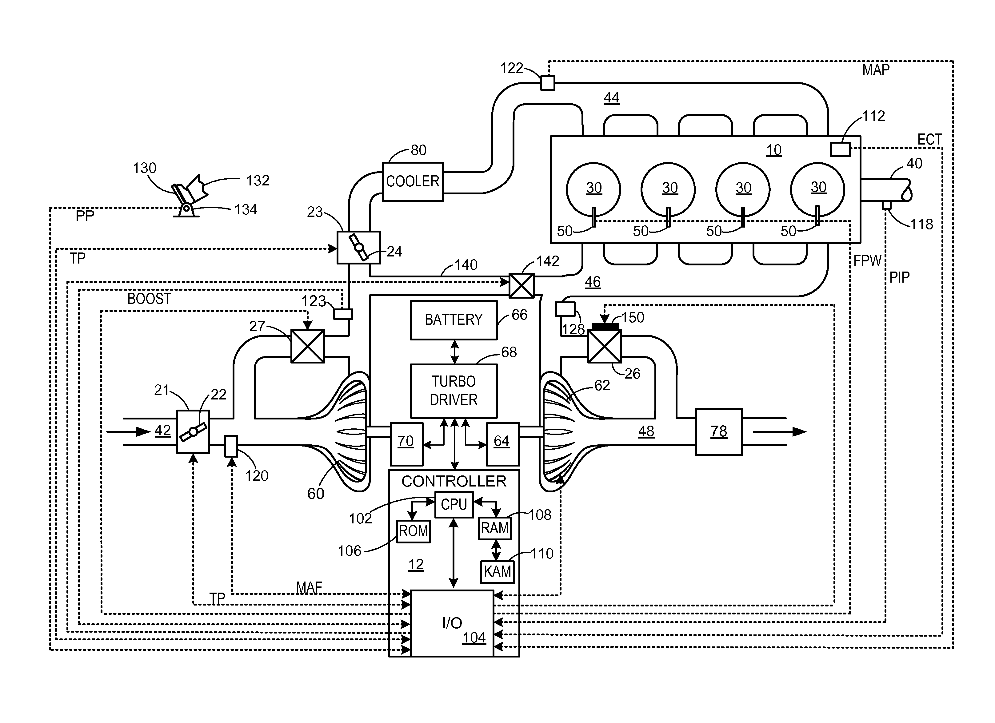
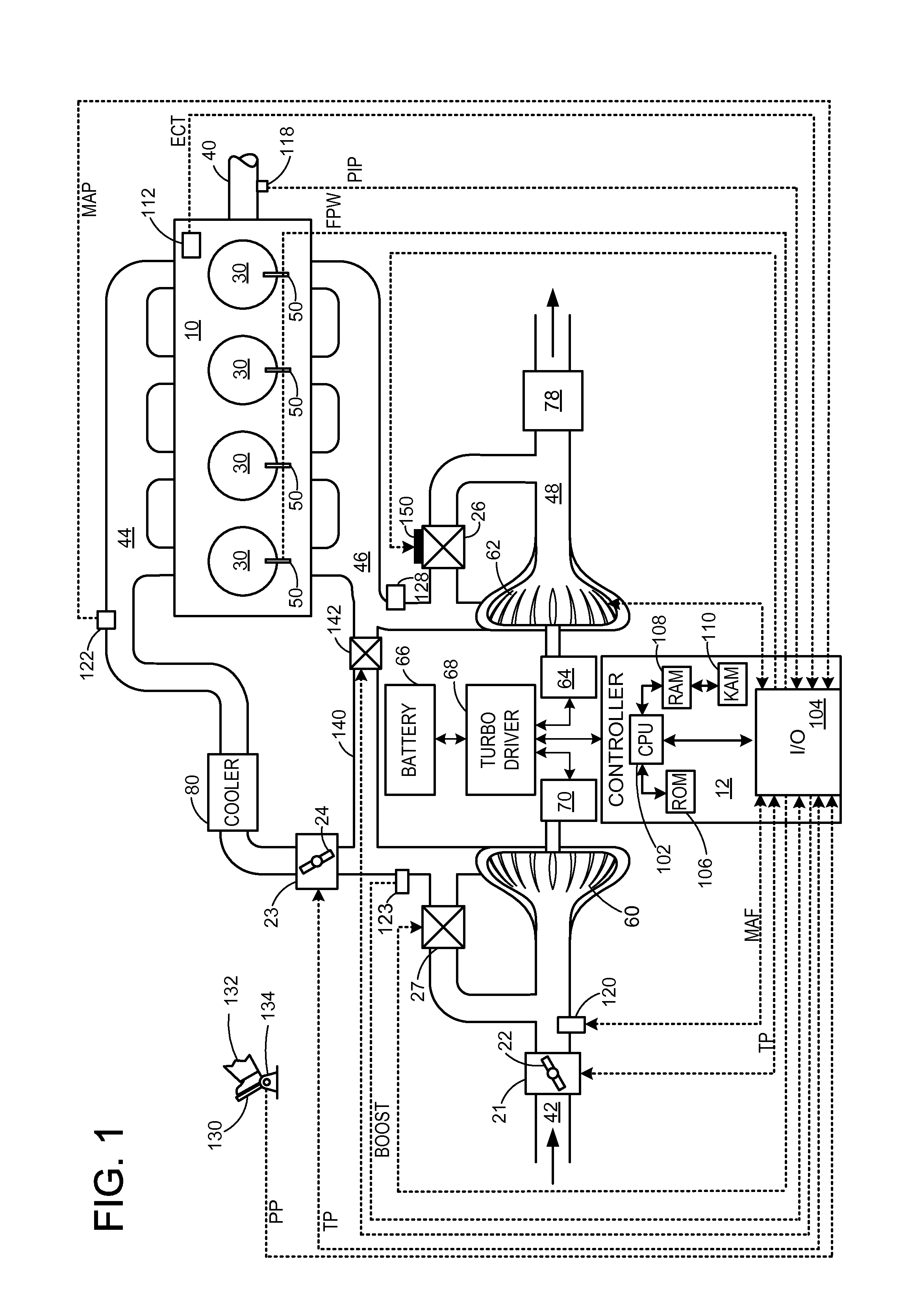
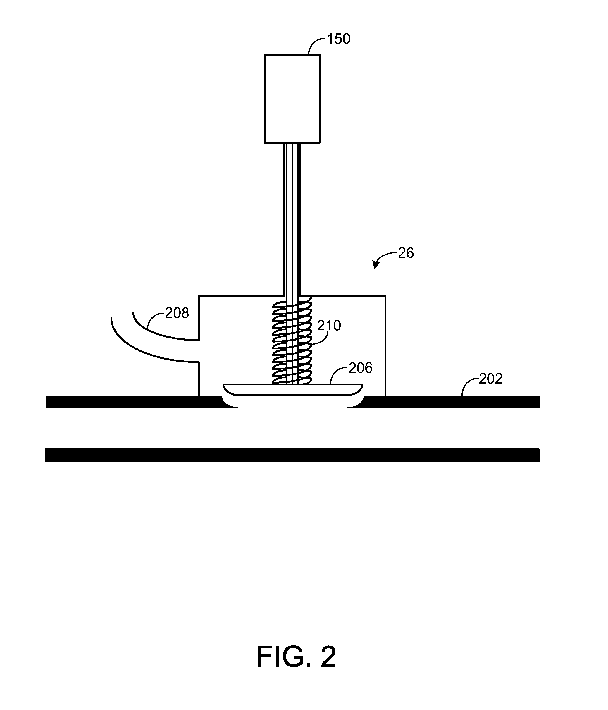
The patent text describes how turbochargers can be used to improve engine performance. A turbocharger has a compressor and a turbine that work together to boost the pressure and flow of air into the engine. The wastegate valve controls the amount of gas reaching the turbine, and an electronic actuator controls the wastegate position to achieve the desired boost. The invention includes a spring that ensures enough boost is provided even if the electronic actuator fails. This design reduces power consumption and enables the size of the electronic actuator to be reduced, which means the electric actuator need not be over-sized to account for wastegate degradation. This is particularly useful for downsized engines where space is limited.

Problems solved by technology

The inventors herein have recognized a problem with such approaches utilizing electric actuators to control the position of a wastegate valve.
In downsized engines, loss of wastegate valve control due to a degraded actuator may cause insufficient boost to be delivered to the engine.
In this case, the engine may not supply the desired level of torque and output.
Thus, the degree of downsizing of the engine may be limited due to wastegate degradation concerns.
For example, loss in wastegate valve control may cause insufficient boost to be delivered to an engine, particularly when the wastegate valve is pushed into a partially open position due to exhaust flow pressure and flow forces.
In this case, the degraded actuator cannot supply sufficient closing force to the valve.

Method used


Image

  • Method for controlling a turbocharger arrangement with an electric actuator and spring
  • Method for controlling a turbocharger arrangement with an electric actuator and spring
  • Method for controlling a turbocharger arrangement with an electric actuator and spring

Examples


Embodiment Construction

[0015]In boosted engines, electronic wastegate actuators may provide precise output to achieve delivery of a desired boost to the engine. Degradation in the electric actuator, for example due to a loss of power, may reduce accurate control of a wastegate valve and limit engine output power / torque. If the actuator degrades when the wastegate valve is in a partially open position, for example, adequate boost may not be supplied to the engine which then cannot provide the desired output. Such a problem is particularly applicable to downsized engines whose dimensions are reduced to improve fuel economy. In downsized engines, a turbocharger may be included to recover the performance loss due to downsizing. If an electric actuator controlling the turbocharger degrades, boost may not be sufficiently provided to the engine, and the engine cannot provide the desired output. Such downsized engines are consequently dimensioned to account for wastegate actuator degradation, limiting the extent ...


PUM

PropertyMeasurementUnit
Forceaaaaaaaaaa
Pressureaaaaaaaaaa
Currentaaaaaaaaaa

Abstract

Various methods for controlling a wastegate with an electric actuator including a bias are provided. In one example, the actuator is supplied with a first current when moving a wastegate valve toward a fully open position, and is supplied with a second current when moving a wastegate toward a fully closed position. The methods may ensure appropriate supply of boost to an engine even in the event of wastegate degradation while enabling engine downsizing.

Description

FIELD[0001]The disclosure relates to a method for controlling a turbocharger arrangement of an internal combustion engine with an electric actuator and spring.BACKGROUND AND SUMMARY[0002]Engines may use a turbocharger to improve engine torque / power output density. In one example, a turbocharger may include a compressor and a turbine connected by a drive shaft, where the turbine is coupled to an exhaust manifold side and the compressor is coupled to an intake manifold side. In this way, the exhaust-driven turbine supplies energy to the compressor to increase the pressure in the intake manifold (e.g. boost, or boost pressure) and to increase the flow of air into the engine. The boost may be controlled by adjusting the amount of gas reaching the turbine, for example with a wastegate. The wastegate valve may be controlled based on operating conditions to achieve the desired boost. In one example, the wastegate valve may be an electronic wastegate controlled by an associated electric act...

Claims


Application Information

Patent Timeline
IPC IPC(8): F02D23/00B23P6/00
CPCF02B37/186Y02T10/12Y10T29/49233
Inventor KARNIK, AMEY Y.WANG, YANKOKOTOVIC, VLADIMIR V.
Owner FORD GLOBAL TECH LLC
Learn More