Wastegate valve seat position determination

a technology of wastegate valve and seat position, which is applied in the direction of electric control, combustion engines, machines/engines, etc., can solve the problems of reducing the accuracy affecting the operation of the wastegate valve, and the linkage may be subject to significant forces, etc., to increase the torque/power output density of the engine, increase the pressure, and increase the flow of air into the engine.

Active Publication Date: 2015-08-27
FORD GLOBAL TECH LLC
View PDF3 Cites 24 Cited by
  • Summary
  • Abstract
  • Description
  • Claims
  • Application Information

AI Technical Summary

Benefits of technology

[0002]Some internal combustion engines utilize a compression device such as a turbocharger to increase engine torque / power output density. In one example, a turbocharger may include a compressor and a turbine connected by a drive shaft, where the turbine is coupled to an exhaust manifold side of an engine and the compressor is coupled to an intake manifold side of the engine. In this way, the exhaust-driven turbine supplies energy to the compressor to increase the pressure (e.g. boost, or boost pressure) in the intake manifold and to increase the flow of air into the engine. The boost may be controlled by adjusting the amount of gas reaching the turbine, for example with a wastegate. An actuator may be operatively coupled via a linkage to a wastegate valve and driven to position the wastegate valve anywhere between a fully open position and a fully closed position (e.g., at a valve seat) to achieve the desired boost based on operating conditions. The actuator may be an electric actuator such as a motor, for example. A position sensor may provide feedback indicating the location of the actuator relative to a reference point. Depending on surrounding conditions, the linkage may be subjected to significantly large forces, vibration, and temperatures.

Problems solved by technology

Depending on surrounding conditions, the linkage may be subjected to significantly large forces, vibration, and temperatures.
Further, lash in the gears and / or linkage can create measurement errors due to the separation of the measurement from the valve itself.
Thus, in some scenarios, thermal and mechanical deformation may occur in a wastegate assembly at regions other than the linkage itself, which may alter the position of a valve seat against which a wastegate valve is abutted at its fully closed position when the supply of boost is not desired.
Such variation in the geometric properties of linkages and valve seats reduce the accuracy with which a wastegate valve may be positioned, in turn reducing the accuracy of boost supply.
Further, a linkage may deflect (e.g., bend) when subject to relatively high forces including those applied to the linkage by an actuator and / or exhaust forces due to the surrounding environment.

Method used


Image

  • Wastegate valve seat position determination
  • Wastegate valve seat position determination
  • Wastegate valve seat position determination

Examples


Embodiment Construction

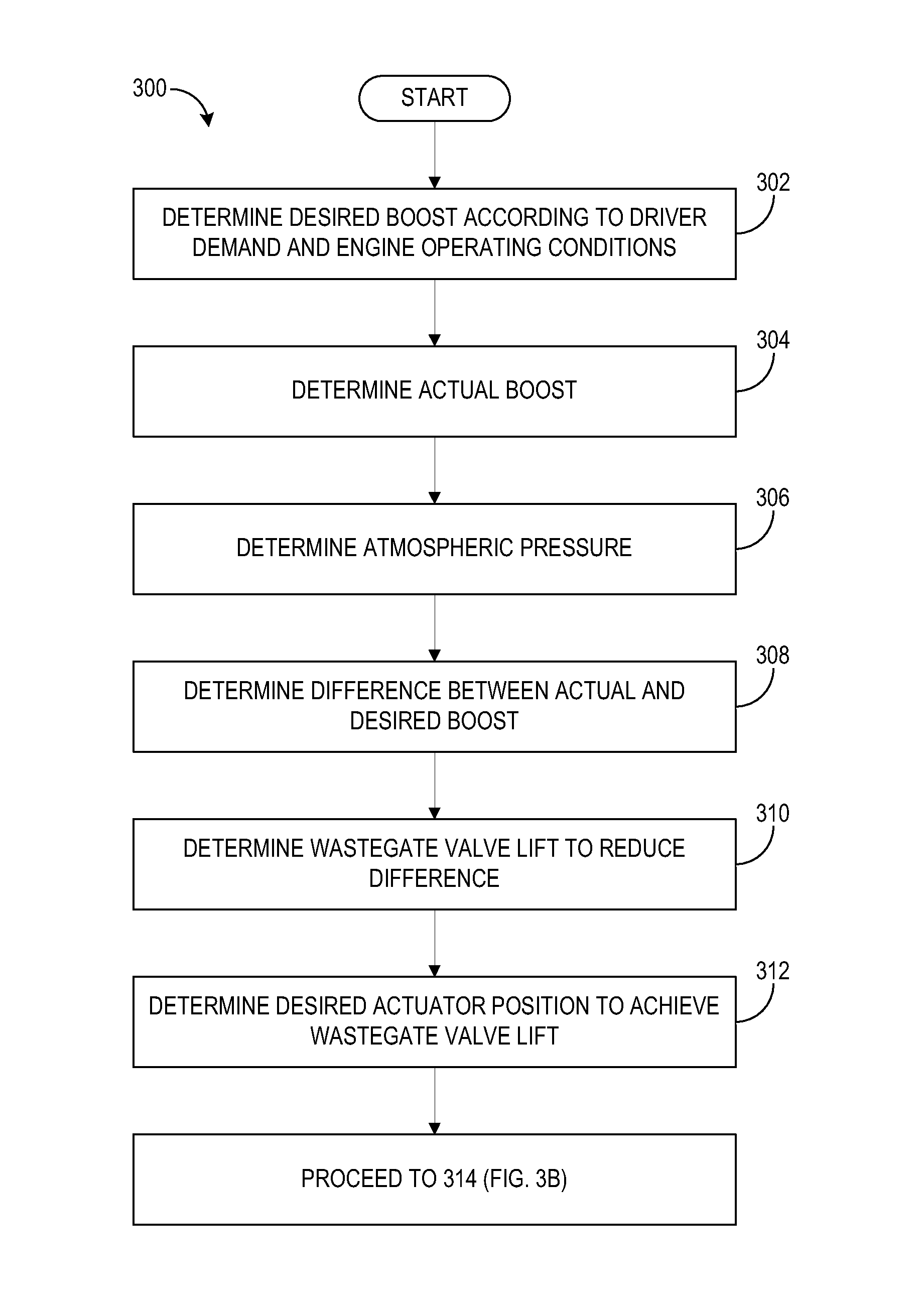
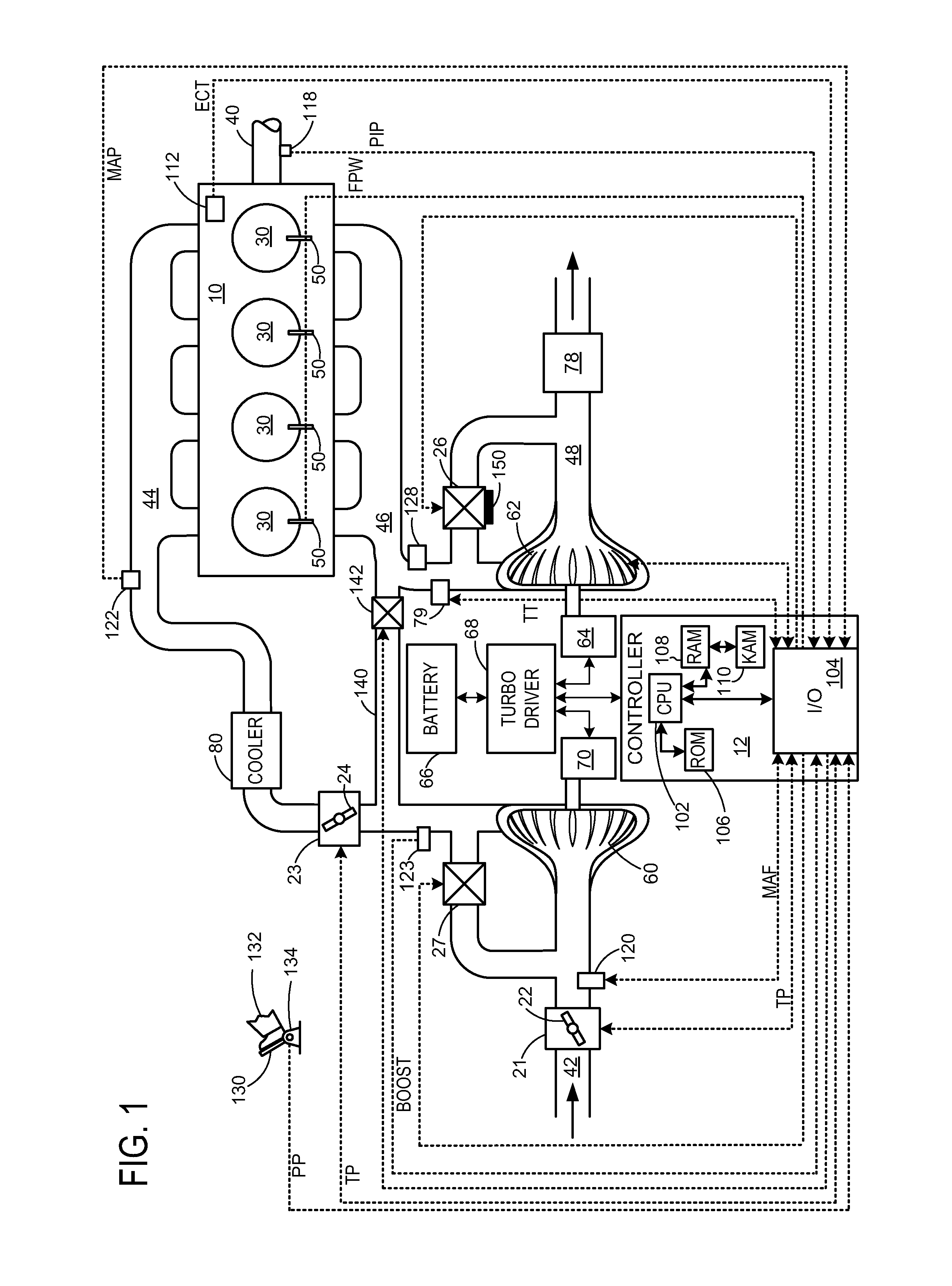
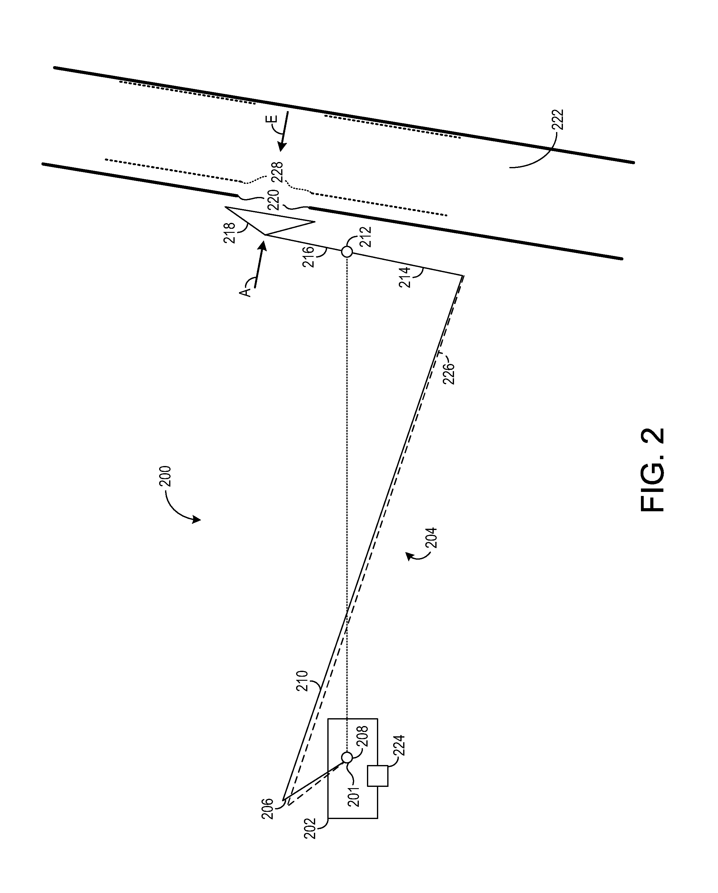
[0019]Compression devices such as a turbocharger may be used to increase the output of an internal combustion engine. A wastegate may in part regulate the boost pressure supplied to the engine by positioning a wastegate valve to thereby control the amount of exhaust gas reaching a turbine of the turbocharger. The wastegate valve may be positioned via an actuator with a linkage disposed therebetween. Accurate wastegate valve positioning and thus accurate boost control may be degraded, however, by a variety of operational factors including thermal deformation in the linkage, valve seat, and overall turbocharger assembly due to high surrounding temperatures, as well as mechanical stress that may deflect or otherwise deform (e.g., bend) portions of the wastegate assembly including the linkage. Thus, strategies designed to mitigate these issues may attempt to compensate two or more constituent factors.

[0020]Various methods for compensating variation in the geometry and position of linkag...


PUM


Abstract

Various methods for compensating variation in the geometry and position of linkages and valve seats in wastegate assemblies are provided. In one example, a method of operating a wastegate in an internal combustion engine comprises, at engine startup, placing a wastegate valve at a seat, recording a position of the seat and associating the seat position with one or more operating parameters, and modifying a position of a wastegate actuator based on the seat position throughout engine operation.

Description

FIELD[0001]The disclosure relates to control of a wastegate in a turbocharger.BACKGROUND AND SUMMARY[0002]Some internal combustion engines utilize a compression device such as a turbocharger to increase engine torque / power output density. In one example, a turbocharger may include a compressor and a turbine connected by a drive shaft, where the turbine is coupled to an exhaust manifold side of an engine and the compressor is coupled to an intake manifold side of the engine. In this way, the exhaust-driven turbine supplies energy to the compressor to increase the pressure (e.g. boost, or boost pressure) in the intake manifold and to increase the flow of air into the engine. The boost may be controlled by adjusting the amount of gas reaching the turbine, for example with a wastegate. An actuator may be operatively coupled via a linkage to a wastegate valve and driven to position the wastegate valve anywhere between a fully open position and a fully closed position (e.g., at a valve se...

Claims


Application Information

Patent Timeline
Patent Type & Authority Applications(United States)
IPC IPC(8): F02B37/18
CPCF02B37/186F02B37/16F02D41/0007F02D41/062F02D41/2438F02D41/2464F02D41/248Y02T10/12
Inventor WANG, YANKOKOTOVIC, VLADIMIR V.KARNIK, AMEY Y.LUEHRSEN, ERICMCCONVILLE, GREGORY PATRICK
Owner FORD GLOBAL TECH LLC
Why Eureka
Try Eureka