Vacuum-actuated wastegate

a wastegate and vacuum technology, applied in the direction of combustion engines, valve details, valve arrangements, etc., can solve the problems of fuel waste, inability to provide vacuum to actuate the wastegate etc., to improve the torque/power output density of the engine, increase the pressure in the intake manifold, and increase the flow of air into the engin

Active Publication Date: 2014-05-22
FORD GLOBAL TECH LLC
View PDF7 Cites 12 Cited by
  • Summary
  • Abstract
  • Description
  • Claims
  • Application Information

AI Technical Summary

Benefits of technology

[0002]Turbochargers may improve engine torque / power output density. A turbocharger may include a compressor and a turbine connected by a drive shaft, where the turbine is coupled to an exhaust manifold side and the compressor is coupled to an intake manifold side. In this way, the exhaust-driven turbine supplies energy to the compressor to increase the pressure in the intake manifold (e.g. boost, or boost pressure) and to increase the flow of air into the engine. The boost may be controlled by adjusting the amount of gas reaching the turbine, for example with a wastegate.

Problems solved by technology

While vacuum-actuated wastegates may provide robust wastegate control during conditions of high engine vacuum, during higher-boost conditions, the engine intake manifold vacuum used to provide vacuum to actuate the wastegate is not available.
A separate vacuum pump may be provided to supply the needed vacuum when engine vacuum is not available, thus wasting fuel.

Method used


Image

  • Vacuum-actuated wastegate
  • Vacuum-actuated wastegate
  • Vacuum-actuated wastegate

Examples


Embodiment Construction

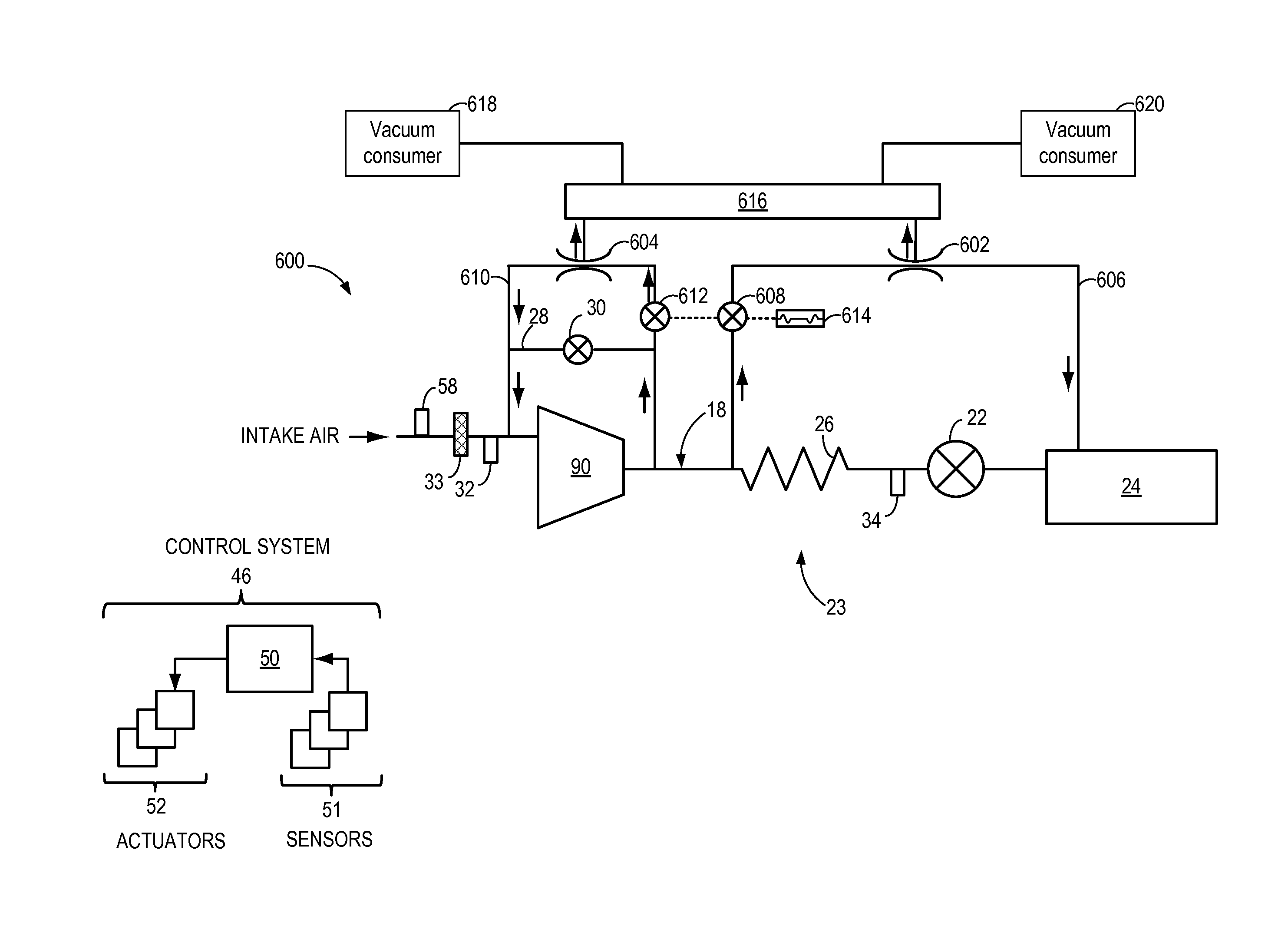
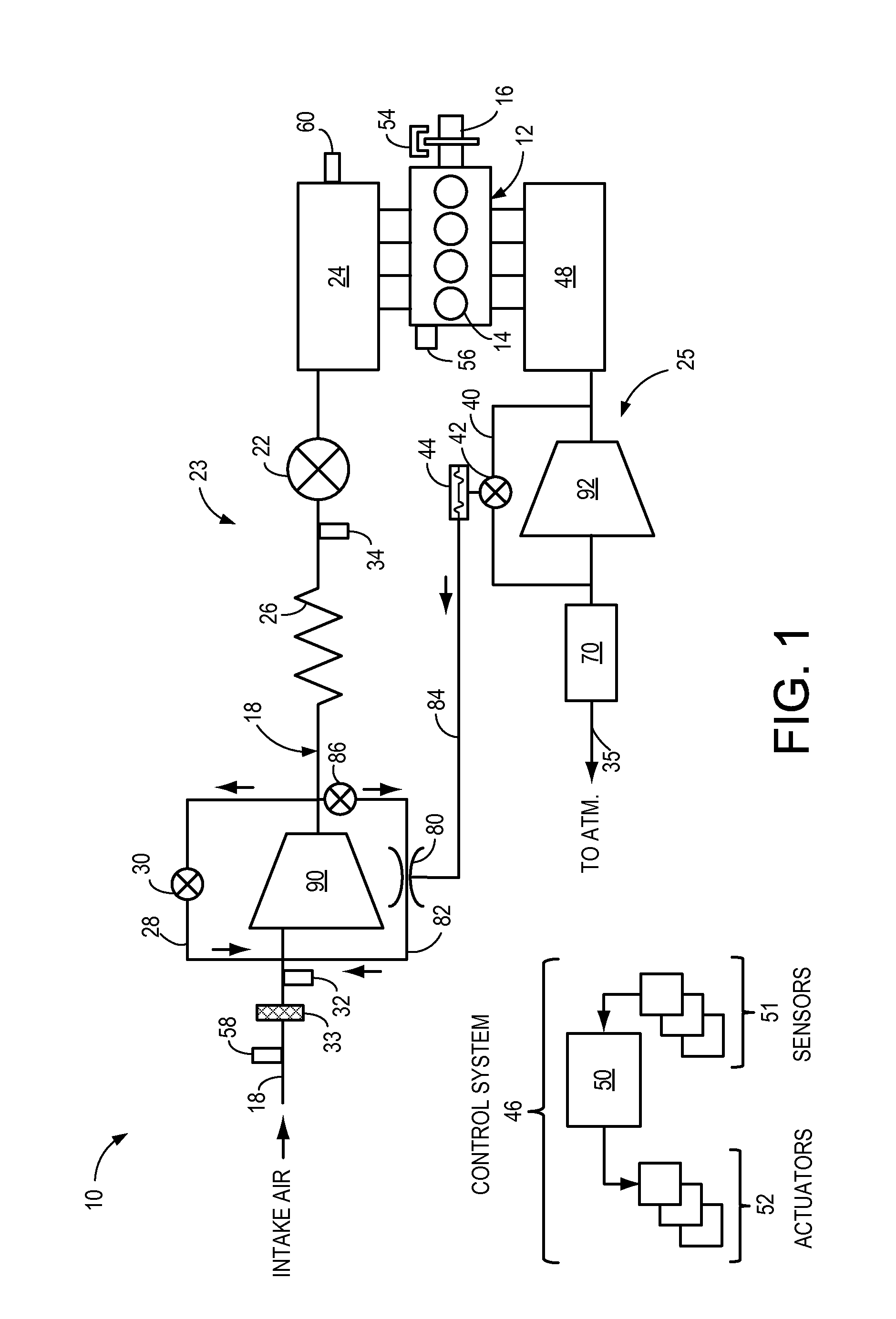
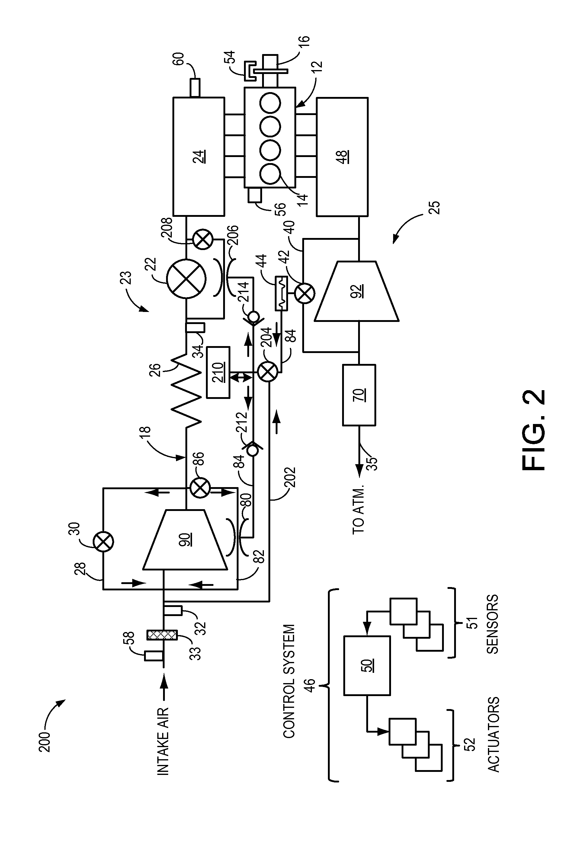
[0016]Wastegates may provide boost control by bypassing exhaust around a turbine. To provide wastegate actuation under a variety of engine conditions, the boost pressure acting as a wastegate control signal may also be used to generate vacuum to actuate the wastegate. An ejector positioned in either the compressor or the turbine bypass flow may generate vacuum that is directed to the wastegate actuator. Alternatively, the ejector may be placed between other suitable pressure differences in the exhaust conduit, the air conduit, or a combination of both. Thus, when excess boost is available for vacuum generation via the ejector, the wastegate is opened. To provide for a variable boost limit, a vent valve may be present to vent some or the entire vacuum away from the actuator. Further, to actuate the wastegate under low or no boost conditions, the actuator may be provided with intake manifold vacuum, supplied directly from the intake manifold or produced from an ejector coupled across ...


PUM


Abstract

Embodiments for vacuum generation are provided. In one example, a method comprises when boost is below a threshold, generating vacuum with an actuator in a first position by flowing air from a compressor outlet to an intake manifold through a first ejector, and when boost is above the threshold, generating vacuum with the actuator in a second position by flowing air from the compressor outlet to a compressor inlet through a second ejector. In this way, vacuum may be generated by more than one ejector via actuation of a common actuator.

Description

FIELD[0001]The present disclosure relates to an internal combustion engine.BACKGROUND AND SUMMARY[0002]Turbochargers may improve engine torque / power output density. A turbocharger may include a compressor and a turbine connected by a drive shaft, where the turbine is coupled to an exhaust manifold side and the compressor is coupled to an intake manifold side. In this way, the exhaust-driven turbine supplies energy to the compressor to increase the pressure in the intake manifold (e.g. boost, or boost pressure) and to increase the flow of air into the engine. The boost may be controlled by adjusting the amount of gas reaching the turbine, for example with a wastegate.[0003]Wastegates may be actuated pneumatically, hydraulically, or electrically. In one example, a wastegate may be actuated via boost pressure produced by the turbocharger. However, it may be advantageous to open the wastegate during low- or no-boost conditions, in order to reduce pumping losses and improve fuel economy....

Claims


Application Information

Patent Timeline
Patent Type & Authority Applications(United States)
IPC IPC(8): F16K31/12
CPCF02B37/186Y02T10/12F16K31/12
Inventor ROLLINGER, JOHN ERICBELL, DAVIDULREY, JOSEPH NORMANPURSIFULL, ROSS DYKSTRA
Owner FORD GLOBAL TECH LLC
Why Eureka
Try Eureka