
Solar cell module, method for manufacturing solar cell module, and tab wire for thin film solar cells

Inactive Publication Date: 2014-04-17
DEXERIALS CORP
View PDF2 Cites 4 Cited by
  • Summary
  • Abstract
  • Description
  • Claims
  • Application Information

AI Technical Summary

Benefits of technology

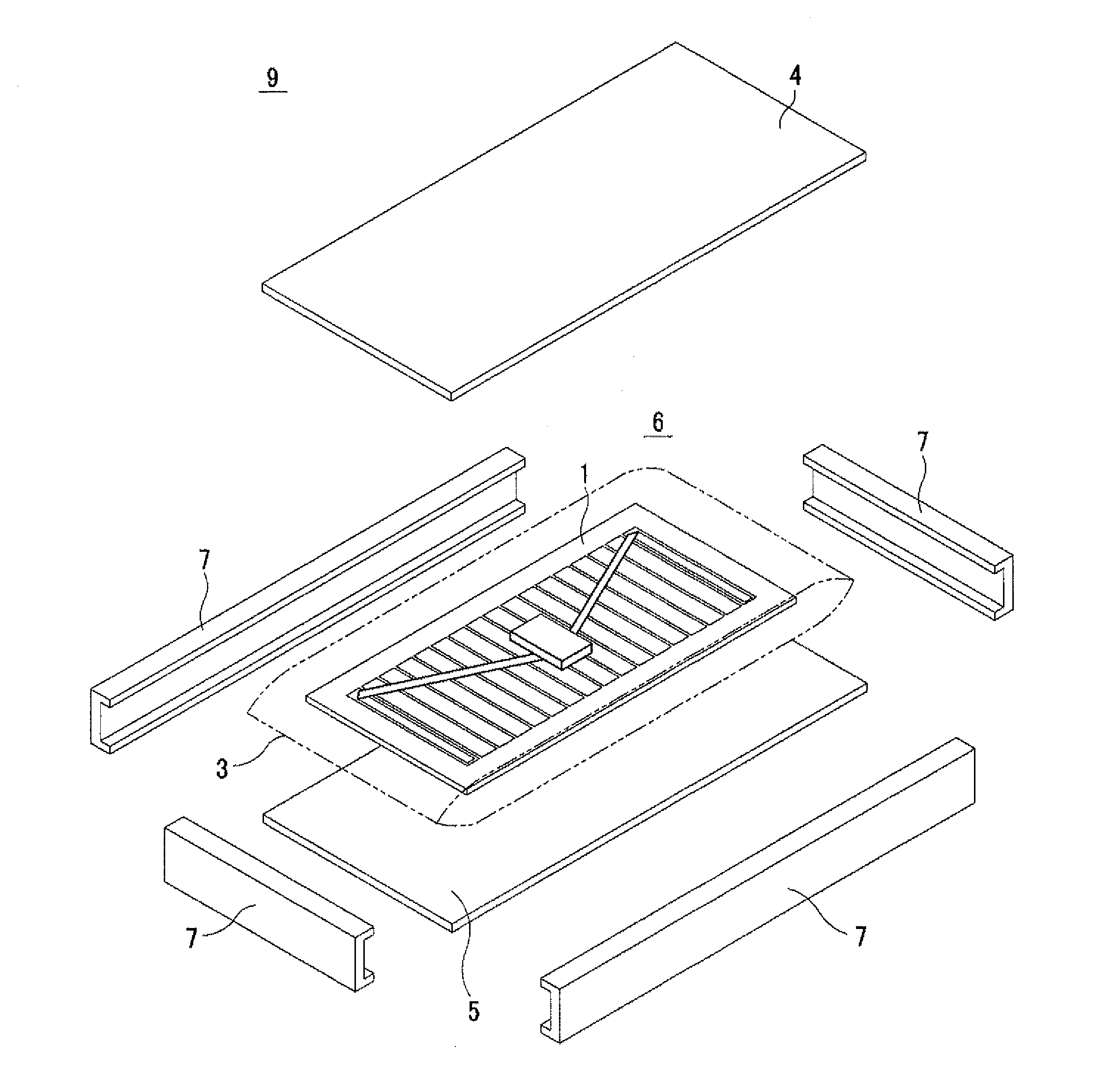
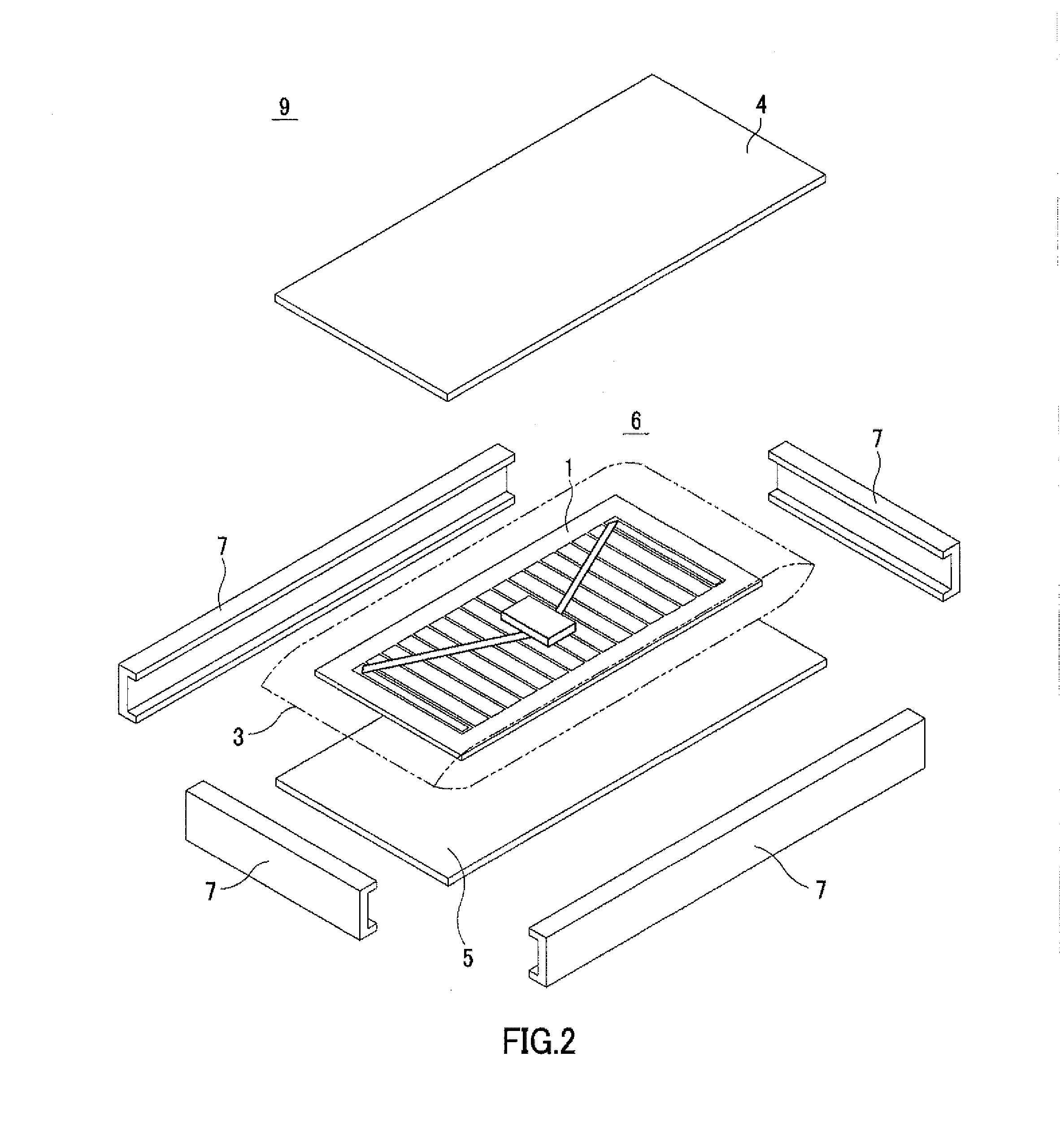
The present invention provides a solar cell that ensures connection reliability between the positive electrode collector tab wire and the terminal box tab wire for a long period of time. The solar cell includes a solar cell with an electrode, a collector tab unit, a terminal box tab unit, and a tab wire. The tab wire connects the collector tab unit to the solar cell and the terminal box tab unit through a folded part. A method for manufacturing the solar cell includes the steps of preparing a tab wire, connecting the collector tab unit to the electrode of the solar cell, forming the terminal box tab unit on the solar cell, and connecting the terminal box tab unit to a terminal box. The use of ultrasonic solder connection and a laser scribing treatment for the joining medium causes degradation in power generation efficiency. By providing a solar cell with a connection layer between the collector tab unit and the terminal box tab unit, and using a continuous structure through a folded part, the present invention ensures reliable connection and efficient power generation.

Problems solved by technology

Since a portion subjected to a laser scribing treatment fails to devote to power generation, causing degradation in power generating efficiency.
Moreover, in the thin-film solar cell 100 shown in FIG. 10, a charge is concentrated on the connection portion between the positive electrode collector tab wire 105 as well as the negative electrode collector tab wire 106 and the terminal box tab wire 111, resulting in a problem of a reduction in the power generation efficiency due to an increase of the resistance value.

Method used


Image

  • Solar cell module, method for manufacturing solar cell module, and tab wire for thin film solar cells
  • Solar cell module, method for manufacturing solar cell module, and tab wire for thin film solar cells
  • Solar cell module, method for manufacturing solar cell module, and tab wire for thin film solar cells

Examples


modified example

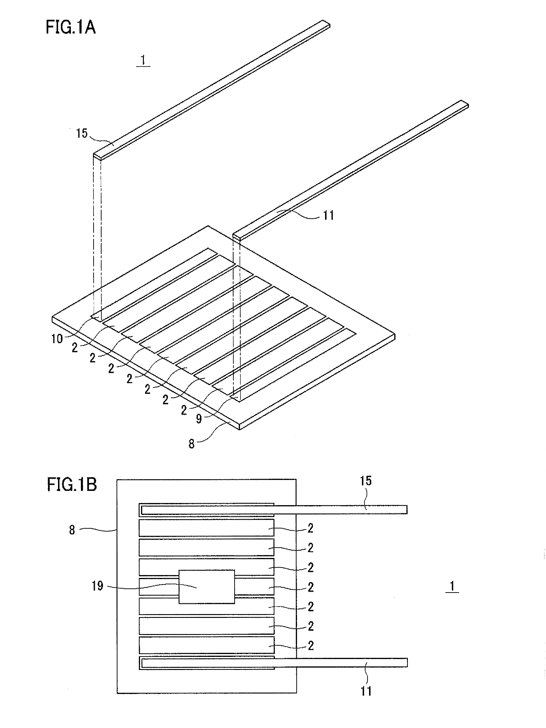
[0079]As shown in FIGS. 8A and 8B, the thin-film solar cell 1 may be configured such that a slit S that extends in the longitudinal direction is formed virtually in the middle portion in the width direction of the positive electrode tab wire 11 or the negative electrode tab wire 15, with folded sections 14 and 18 being formed on one of portions divided by the slit S, and with the tips of the folded sections 14 and 18 serving as the terminal box positive electrode tab unit 13 or the terminal box negative electrode tab unit 17. In this case, the other portion divided by the slit constitutes the positive electrode collector tab unit 12 or the negative electrode collector tab unit 16 together with the portion with no slit S formed therein. Moreover, the positive electrode tab wire 11 and negative electrode tab wire 15 may not necessarily be made longer than the P-type electrode terminal unit 9 and the N-type electrode terminal 10. The length of the slit S is determined on demand dependi...

examples

[0090]Next, the following description will discuss examples of the thin-film solar cell 1 using the positive electrode tab wire 11 and the negative electrode tab wire 15, in comparison with a conventional thin-film solar cell and a thin-film solar cell in which a positive electrode tab wire and a negative electrode tab wire without an insulating layer 21 are used. g

[0091]In any one of samples, a copper foil ribbon having a thickness of 70 μm was used as a base member of the tab wire, and a connection layer was formed on one of surfaces that was connected to an electrode terminal unit of the thin-film solar cell. Moreover, in examples 1 to 6 as well as comparative examples 1 and 2, an insulating layer was also formed on the other surface.

[0092]Moreover, in each of the samples, the same thin-film solar cell (with a photoelectric conversion layer made of amorphous silicon) was used and connections were made to the P-type electrode terminal unit and the N-type electrode terminal unit.

[0...


PUM


Abstract

To ensure connection reliability between a tab wire for a collector and a tab wire for a terminal box over a long period of time. This solar cell module is provided with: a solar cell, on one surface of which an electrode is arranged; and a tab wire, which includes a collector tab unit that is connected onto the electrode of the solar cell with a connection layer interposed therebetween and a terminal box tab unit that is provided on one surface of the solar cell with an insulating layer interposed therebetween, and in this structure, the collector tab unit and the terminal box tab unit are continuously formed via a folded part.

Description

FIELD OF THE INVENTION[0001]This invention relates to a solar cell module in which a positive electrode and a negative electrode are arranged on one of surfaces and a terminal box tab wire is installed thereon, and in particular concerns a solar cell module that can efficiently connect the positive electrode as well as negative electrode and the terminal box, and a method for manufacturing such a solar cell module.[0002]The present application asserts priority rights based on JP Patent Application 2011-119686 filed in Japan on May 27, 2011. The total contents of disclosure of the patent application of the senior filing date are to be incorporated by reference into the present application.BACKGROUND OF THE INVENTION[0003]In recent years, along with a trend in which a reduction in environmental load becomes a global subject, big expectations have been put on the photovoltaic power generation as a clean and reproducible energy. At present, the main trend for manufacturing solar cells c...

Claims


Application Information

Patent Timeline
IPC IPC(8): H01L31/02H01L31/18
CPCH01L31/18H01L31/02013H01L31/0201H02S40/34Y02E10/50
Inventor NISHIMOTO, MASAHIRO
Owner DEXERIALS CORP
Learn More