Thin film magnetic head

Active Publication Date: 2008-06-19
TDK CORPARATION
View PDF1 Cites 24 Cited by
  • Summary
  • Abstract
  • Description
  • Claims
  • Application Information

AI Technical Summary

Benefits of technology

[0008]When the external environmental temperature is high, the resistance value of the temperature correcting resistor having a negative resistance temperature coefficient decreases. When the external environmental temperature is low, the resistance value of the temperature correcting resistor increases. Therefore, in a closed circuit composed of the temperature correcting resistor and the heater, when the external environmental temperature increases, the amount of current flowing through the temperature correcting resistor increases, and the amount of current flowing through the heater decreases, resulting in a reduction in the amount of heat generated from the heater. In this case, the amount of protrusion of the element portion due to the external environmental temperature increases, but the amount of protrusion of the element portion due to heat generated from the heater is reduced. As a result, it is possible to prevent a variation in the amount of protrusion of the element portion even when the external environmental temperature varies.
[0009]In the thin film magnetic head according to the above-mentioned aspect, preferably, the temperature correcti

Problems solved by technology

Therefore, when the external environmental temperature is high during the operation of the heater, there is a fear that the element portion will come into contact with a recording medium and the element portion and the recording medium will be damaged.
However, the method of reducing only the amount of heat generated from the heate

Method used


Image

  • Thin film magnetic head
  • Thin film magnetic head
  • Thin film magnetic head

Examples


Example

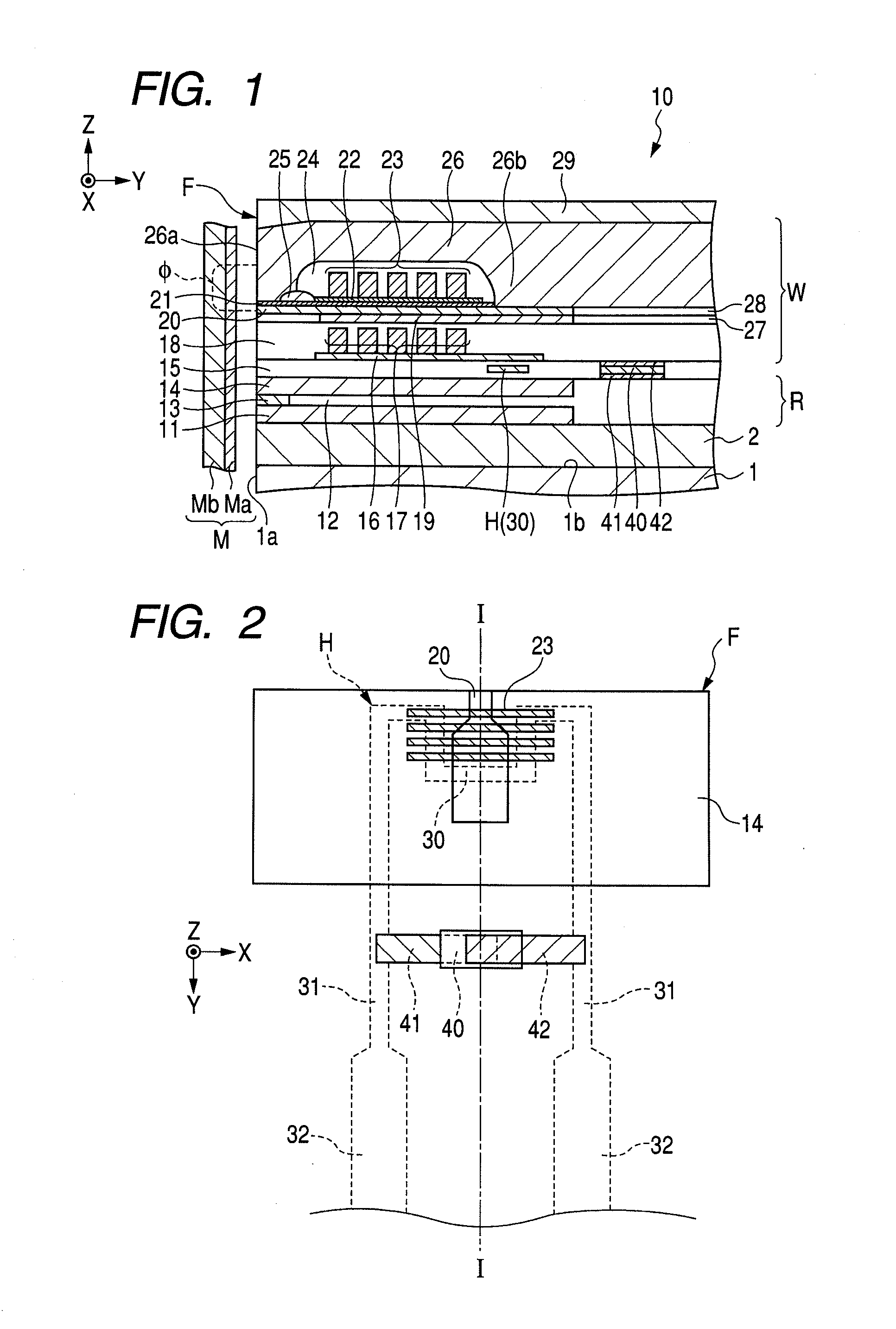
[0018]FIGS. 1 and 2 show a cross-sectional view and a plan view illustrating the structure of a thin film magnetic head according to an embodiment of the invention. In FIGS. 1 and 2, an X direction indicates a track width direction, a Y direction indicates a height direction, and a Z direction indicates a direction in which layers of the thin film magnetic head are laminated.

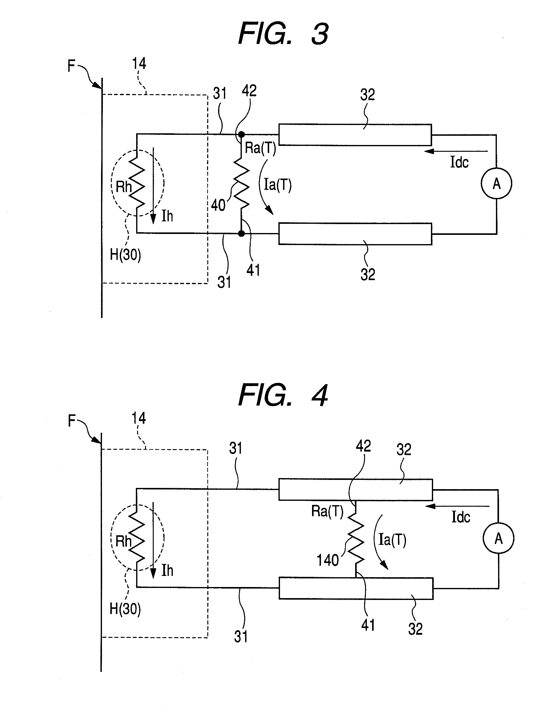
[0019]The thin film magnetic head according to this embodiment includes a head structure 10 formed by laminating a thin film on a trailing side surface 1b of a slider 1. The head structure 10 includes a reproducing head R that reads out magnetic recording information from a recording medium M using magnetoresistance, a vertical recording type recording head W that vertically applies a recoding magnetic field Φ to the recording medium M to record magnetic information on the recording medium, and a heater H that is supplied with power and generates heat.

[0020]The recording medium M has a hard film Ma having high r...


PUM


Abstract

A thin film magnetic head is disclosed that is capable of preventing the contact between an element portion and a recording medium and a variation in the amount of protrusion of the element portion. A thin film magnetic head includes: a reproducing element; a recording element that is formed on the reproducing element; a heater that is supplied with power and generates heat to expand at least one of the reproducing element and the recording element such that the reproducing element and/or the recording element protrude toward a recording medium; and a temperature correcting resistor that is connected in parallel to the heater and has a negative resistance temperature coefficient.

Description

CLAIM OF PRIORITY[0001]This application claims benefit of the Japanese Patent Application No. 2006-338069 filed on Dec. 15, 2006, which is hereby incorporated by reference.BACKGROUND OF THE INVENTION[0002]1. Field of the Invention[0003]The present invention relates to a thin film magnetic head having a heater that generates heat to expand a reproducing element and a recording element toward a recording medium.[0004]2. Description of the Related Art[0005]A thin film magnetic head used for, for example, a magnetic disk apparatus includes a reproducing element that reads out magnetic recording information from a recording medium using magnetoresistance and a recording element that applies a recoding magnetic field to the recording medium to record various information items on the recording medium. The reproducing element has a multi-layer film that exhibits magnetoresistance between a lower shield layer and an upper shield layer opposite to each other at a predetermined gap therebetwee...

Claims


Application Information

Patent Timeline
IPC IPC(8): G11B5/39
CPCG11B5/1278G11B5/314Y10T428/1107G11B5/6064G11B5/6005G11B5/3133G11B5/40G11B5/5565G11B5/607
Inventor YAMASHITA, TOMOHIROKAKUHARI, YUYA
Owner TDK CORPARATION
Why Eureka
Try Eureka