DC to DC buck converting controller with programmable on-time period unit

Active Publication Date: 2014-04-17
GREEN SOLUTION TECH CO LTD
View PDF39 Cites 13 Cited by
  • Summary
  • Abstract
  • Description
  • Claims
  • Application Information

AI Technical Summary

Benefits of technology

The invention is a DC to DC buck converting controller that can adjust its programmable on-time period based on a reference signal. This makes it suitable for applications that require different output voltages or modes of operation, and improves the controller's response to changes in output demand. Additionally, the controller can be designed without a pin to obtain output voltage information, which lowers the cost of the controller and its associated circuit board.

Problems solved by technology

During the interval from the time point t1 to a time point t2, the output voltage Vout is temporarily decreased due to that an increased output power provided by the converting circuit is not enough.
However, the output voltage Vout is lower than the original voltage level during an interval from the time point t1 to the time point t3, and so the on-time periods of cycles within the interval are shorter, which is a great disadvantage for transient response.

Method used


Image

  • DC to DC buck converting controller with programmable on-time period unit
  • DC to DC buck converting controller with programmable on-time period unit
  • DC to DC buck converting controller with programmable on-time period unit

Examples


first embodiment

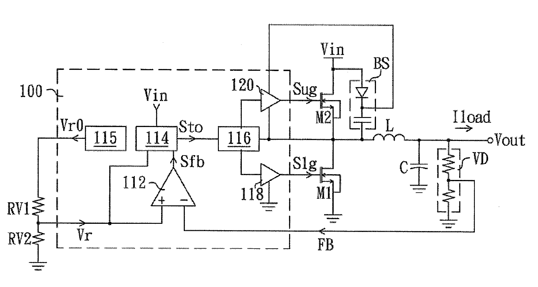
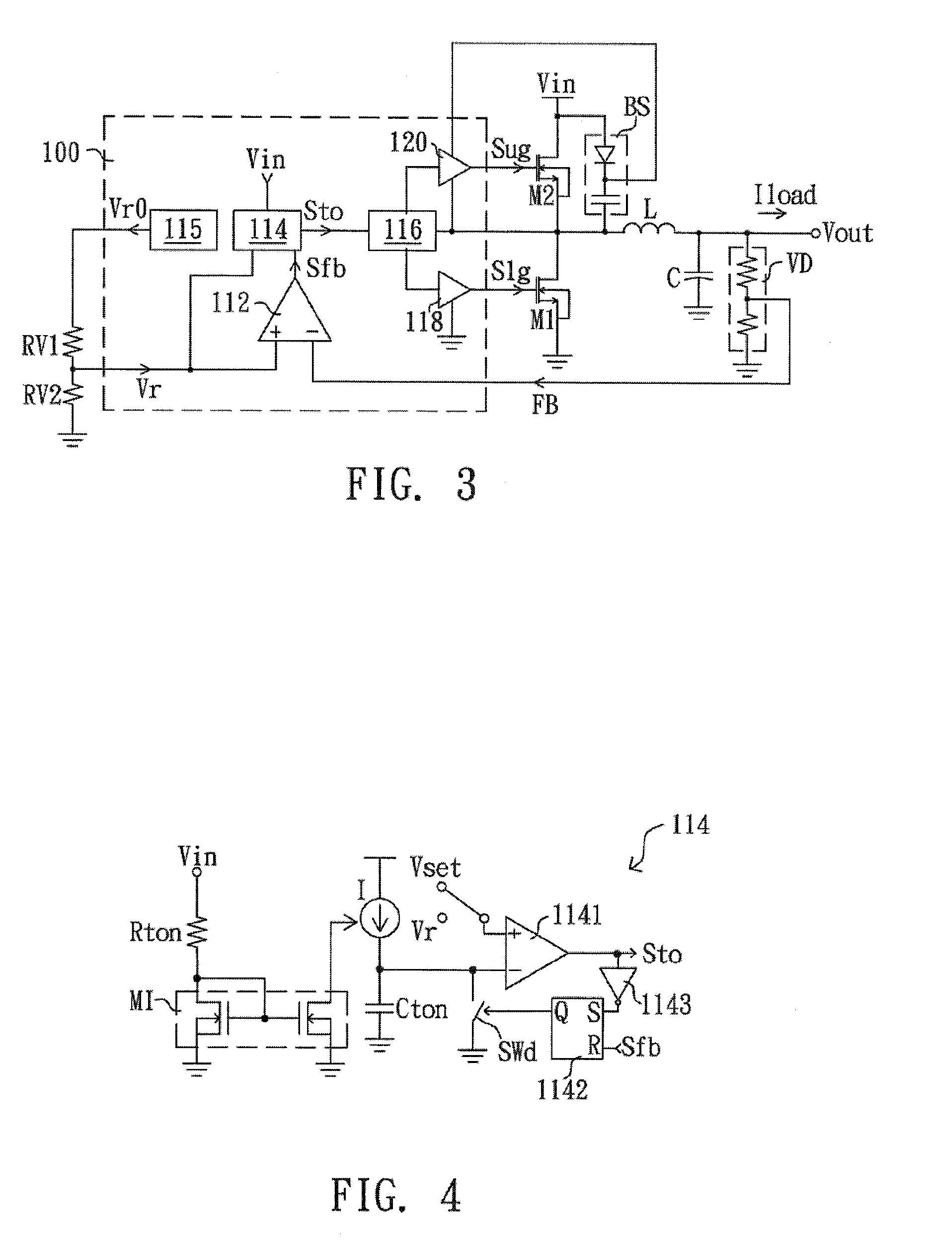
[0023]FIG. 3 is a schematic diagram of a DC to DC buck converting circuit according to the invention. The DC to DC buck converting circuit comprises a controller 100, two switches M1 and M2, an inductance L, a capacitance C, a bootstrap circuit BS and a voltage divider VD. The voltage divider VD detects an output voltage Vout of the DC to DC buck converting circuit and accordingly generates a feedback signal FB. The controller 100 turns the switches M1 and M2 on / off according to the feedback signal FB, so as to make the DC to DC buck converting circuit convert an input voltage Vin into an output voltage Vout which is stabilized at a preset output voltage and provide an output current Iload to a load (not shown).

[0024]The controller 100 comprises a feedback circuit 112, a driving circuit which comprises an on-time period circuit 114, a logic control circuit 116 and two gate driving units 118, 120, which is packaged in a package with a plurality of pins. The feedback circuit 112 compr...

second embodiment

[0029]FIG. 6 is a schematic diagram of a DC to DC buck converting circuit according to the invention. Compared with the embodiment shown in FIG. 3, the controller 200 omits the reference voltage generating circuit 115 and the voltage divider, and adds anti-noise circuit 125. The feedback circuit 112 directly receives the reference voltage Vr through a pin of the package and compares the reference voltage Vr with the feedback signal FB to generate the feedback control signal Sfb. If a digital reference signal indicative of the reference voltage is input through the pin, the controller 200 may adds a digital to analog converter to convert the digital signal into the reference voltage Vr. The anti-noise circuit 125 is coupled between the feedback circuit 112 and the on-time period circuit 114 for avoiding noise interferences in generation of the feedback control signal Sfb. The anti-noise circuit 125 generates a trigger signal Sd to the on-time period circuit 114 when the feedback cont...


PUM


Abstract

A programmable on-time period of a DC to DC buck converting controller is adjusted according to a level of a preset output voltage or a reference signal. Therefore, the DC to DC buck converting controller of the present invention is suitable for any applications with different requests of output voltages or different operating mode.

Description

CROSS-REFERENCE TO RELATED APPLICATION[0001]This application is a continuation-in-part application of and claims the priority benefit of U.S. application Ser. No. 13 / 284,974, filed on Oct. 30, 2011, now pending, which claims the priority benefit of China application serial no. 201110100828.0, filed on Apr. 21, 2011. The entirety of each of the above-mentioned patent applications is hereby incorporated by reference herein and made a part of specification.BACKGROUND OF THE INVENTION[0002]1. Field of the Invention[0003]The present invention relates to a DC to DC buck converting controller, and more particularly a DC to DC buck converting controller with programmable output voltage.[0004]2. Description of Related Art[0005]FIG. 1 is a schematic diagram of a conventional DC to DC buck converting circuit. The DC to DC buck converting circuit comprises a controller 10, two switches M1 and M2, an inductance L, a capacitance C, a bootstrap circuit BS and a voltage divider VD. The voltage divi...

Claims


Application Information

Patent Timeline
IPC IPC(8): H02M3/156H02M1/00
CPCH02M3/156H02M3/1588H02M3/158Y02B70/10H02M1/0022H02M1/0025
Inventor LEE, LI-MINYU, CHUNG-CHESHIU, SHIAN-SUNGSHAO, CHAOGAN, QUAN
Owner GREEN SOLUTION TECH CO LTD
Why Eureka
Try Eureka