
Detecting device and detecting method

a detection device and detection method technology, applied in the direction of selective content distribution, transmission monitoring, instruments, etc., can solve the problems of external power sources damaged, controlled devices crashed, and people normally unaware of the power condition of controlled devices

Inactive Publication Date: 2014-04-17
AVERMEDIA TECH
View PDF1 Cites 1 Cited by
  • Summary
  • Abstract
  • Description
  • Claims
  • Application Information

AI Technical Summary

Benefits of technology

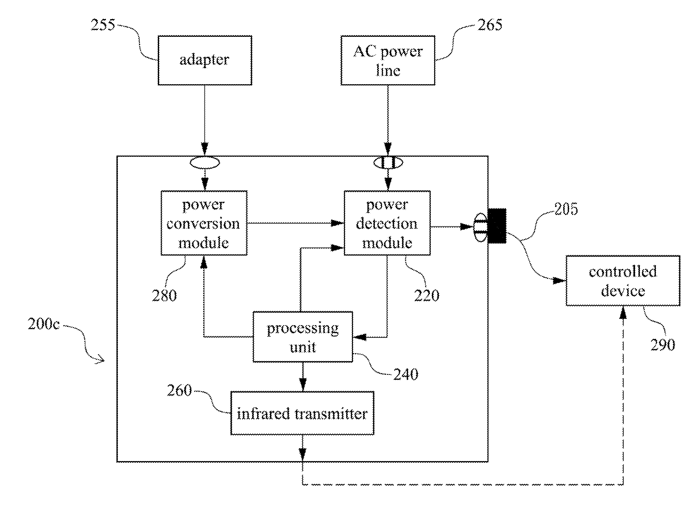
The invention is a detection device that can help users understand the power condition of a controlled device, so they can operate it correctly. This can improve user experience and prevent errors when using the controlled device.

Problems solved by technology

However, in using the remote controls to operate the controlled devices, people are normally unaware of the power condition of the controlled devices.
When the controlled devices malfunction, they cannot determine the malfunction results from that the controlled devices are crashed, external power sources are damaged, or other problems.

Method used


Image

  • Detecting device and detecting method
  • Detecting device and detecting method
  • Detecting device and detecting method

Examples


Embodiment Construction

[0023]Reference will now be made in detail to the present embodiments of the invention, examples of which are illustrated in the accompanying drawings. Wherever possible, the same reference numbers are used in the drawings and the description to refer to the same or like parts.

[0024]The present invention will now be described more fully hereinafter with reference to the accompanying drawings, in which exemplary embodiments of the invention are shown. This invention may, however, be embodied in many different forms and should not be construed as limited to the embodiments set forth herein. Rather, these embodiments are provided so that this disclosure will be thorough and complete, and will fully convey the scope of the invention to those skilled in the art. Like reference numerals refer to like elements throughout.

[0025]As used herein, “around”, “about” or “approximately” shall generally mean within 20 percent, preferably within 10 percent, and more preferably within 5 percent of a ...


PUM


Abstract

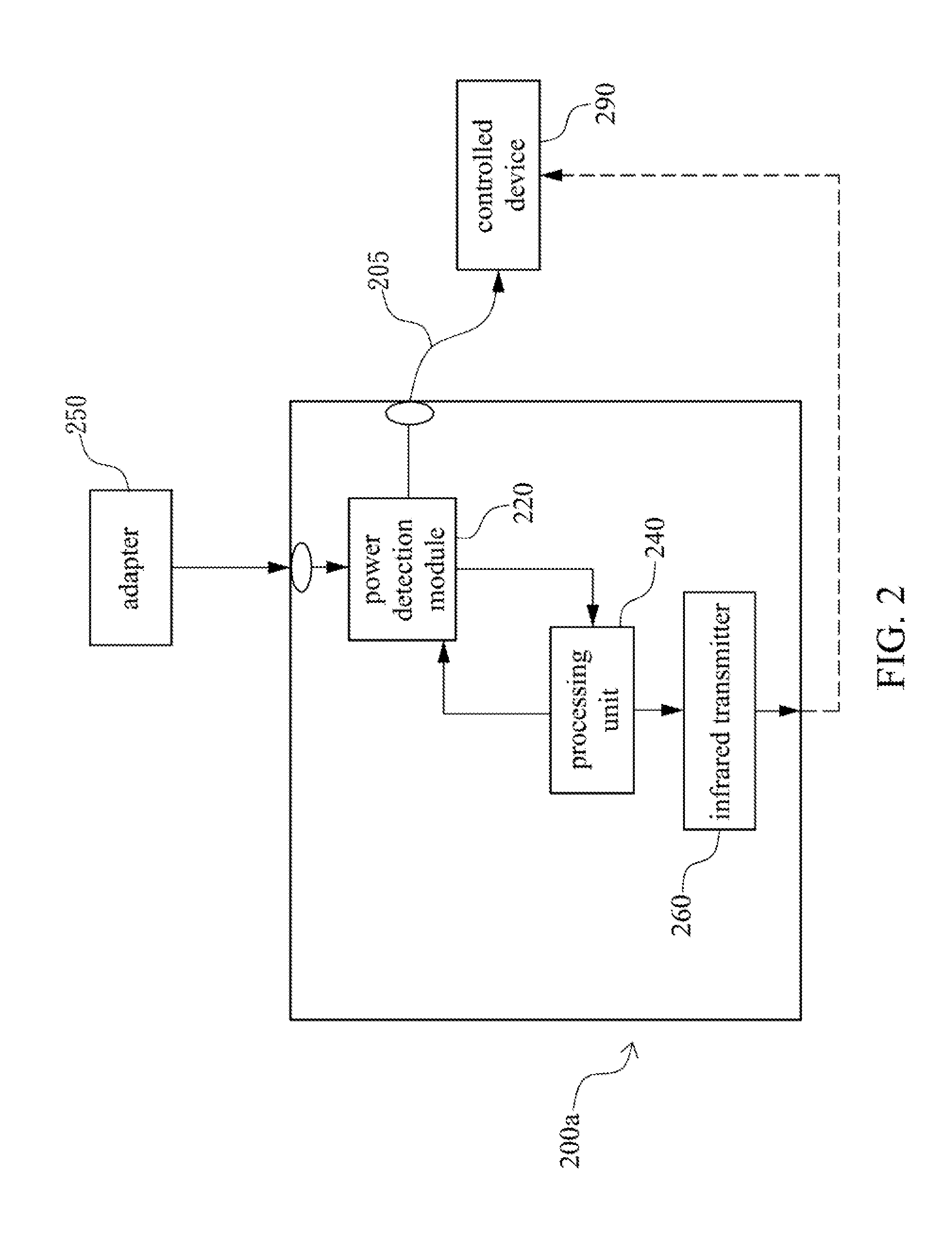
A detection device is electrically connected to a controlled device through a power line and configured for detecting a power condition of the controlled device. The detection device at least includes a power detection module, a processing unit, and an infrared transmitter. The power detection module is configured for detecting an input current transmitted through the power line from the controlled device and converting the input current to an output voltage signal. The processing unit is configured for receiving the output voltage signal and determining the power condition of the controlled device based on a voltage level of the output voltage signal. The infrared transmitter is configured for transmitting an infrared signal based on the determined result of the processing unit to switch the controlled device such that the controlled device performs a corresponding operation. Further, a detecting method is also disclosed.

Description

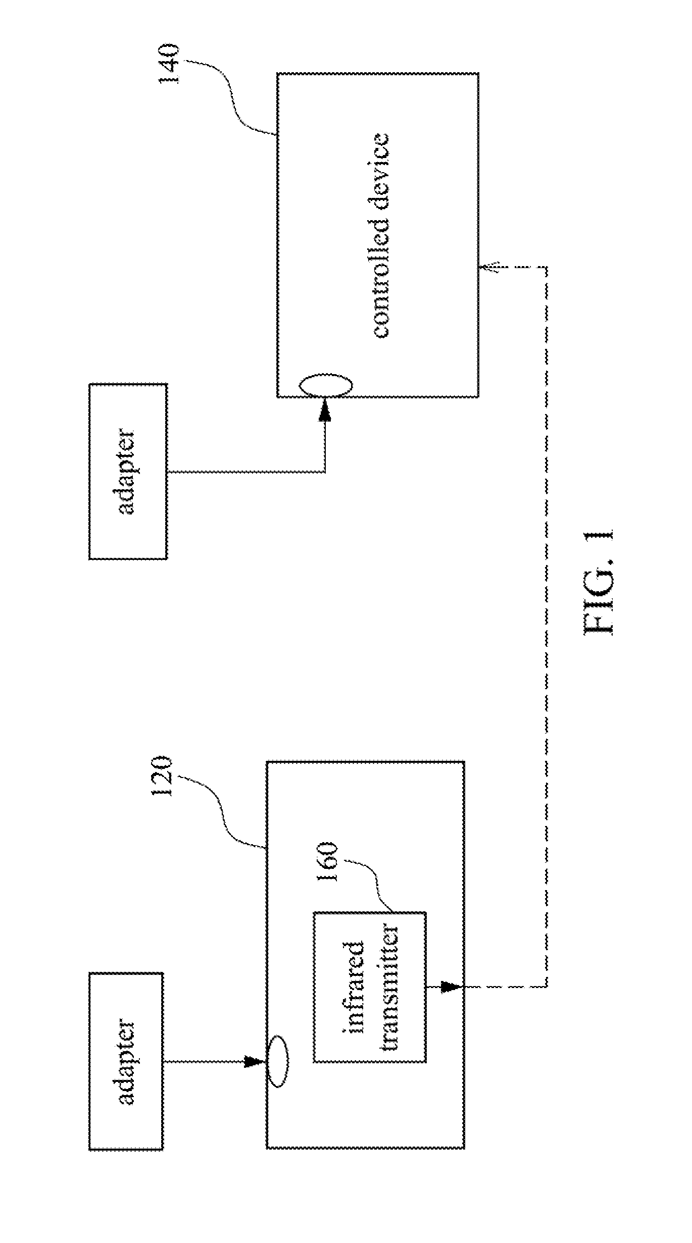
BACKGROUND[0001]1. Field of Invention[0002]The present invention relates to a detection device and a detecting method. More particularly, the present invention relates to a power detection device and a power detecting method.[0003]2. Description of Related Art[0004]With rapid development of technology, electronic devices, hereinafter referred to as controlled devices, for people are capable of being distantly operated by remote controls. For example, the remote control can turn on / off a power source of a recorder, adjust the recorder's volume and frame quality, switch to different working modes of the recorder, and so forth.[0005]FIG. 1 illustrates a circuit diagram of a remote control operates a controlled device. As shown in FIG. 1, instead of touching controlled device 140, remote control 120 can operate controlled device 140 distantly. By using infrared transmitter 160 in remote control 120, remote control 120 can transmit an infrared signal to a receiver of controlled device 14...

Claims


Application Information

Patent Timeline
Patent Type & Authority Applications(United States)
IPC IPC(8): G01R31/00H04B10/08
CPCG01R19/16595H04N21/42221H04N21/44231
Inventor YEH, CHIEN-MINGCHEN, YU-HSIANGLEE, NENG-CHIA
Owner AVERMEDIA TECH
Learn More