Eureka AIR delivers breakthrough ideas for toughest innovation challenges, trusted by R&D personnel around the world.

Connector terminal

Active Publication Date: 2014-04-17
YAZAKI CORP
View PDF91 Cites 18 Cited by
  • Summary
  • Abstract
  • Description
  • Claims
  • Application Information

AI Technical Summary

Benefits of technology

This invention provides a connector terminal that can connect to an electric wire without fail and prevent corrosion at the connection point. This is done by crimping the conductor to the barrel portion of the connector terminal without breaking the covering, thereby maintaining the anticorrosion effect of the conductor. This connector terminal does not require a molding machine or resin, saving costs. Additionally, the connector terminal has a sealing piece that effectively protects the covering of the conductor. Overall, this invention provides a cost-effective solution for connecting wires while ensuring superior anticorrosion performance.

Problems solved by technology

Therefore, the molding machine for performing processing pertaining to the molding step and a resin material for molding purpose are necessary, which adds to costs of facilities and manufacturing costs.

Method used


Image

  • Connector terminal
  • Connector terminal
  • Connector terminal

Examples


Embodiment Construction

[0030]An exemplary embodiment of the invention is hereunder described by reference to the drawings.

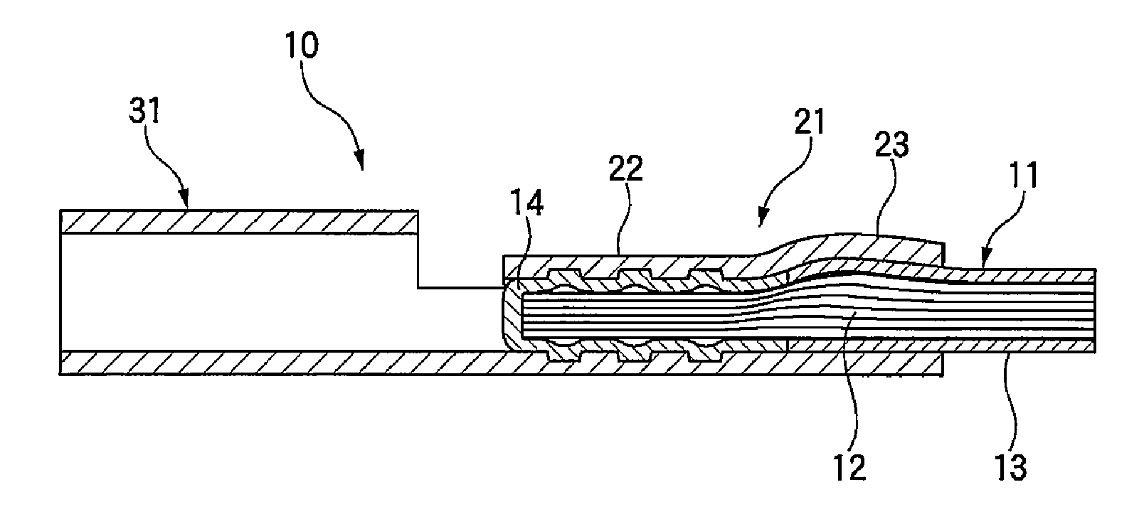
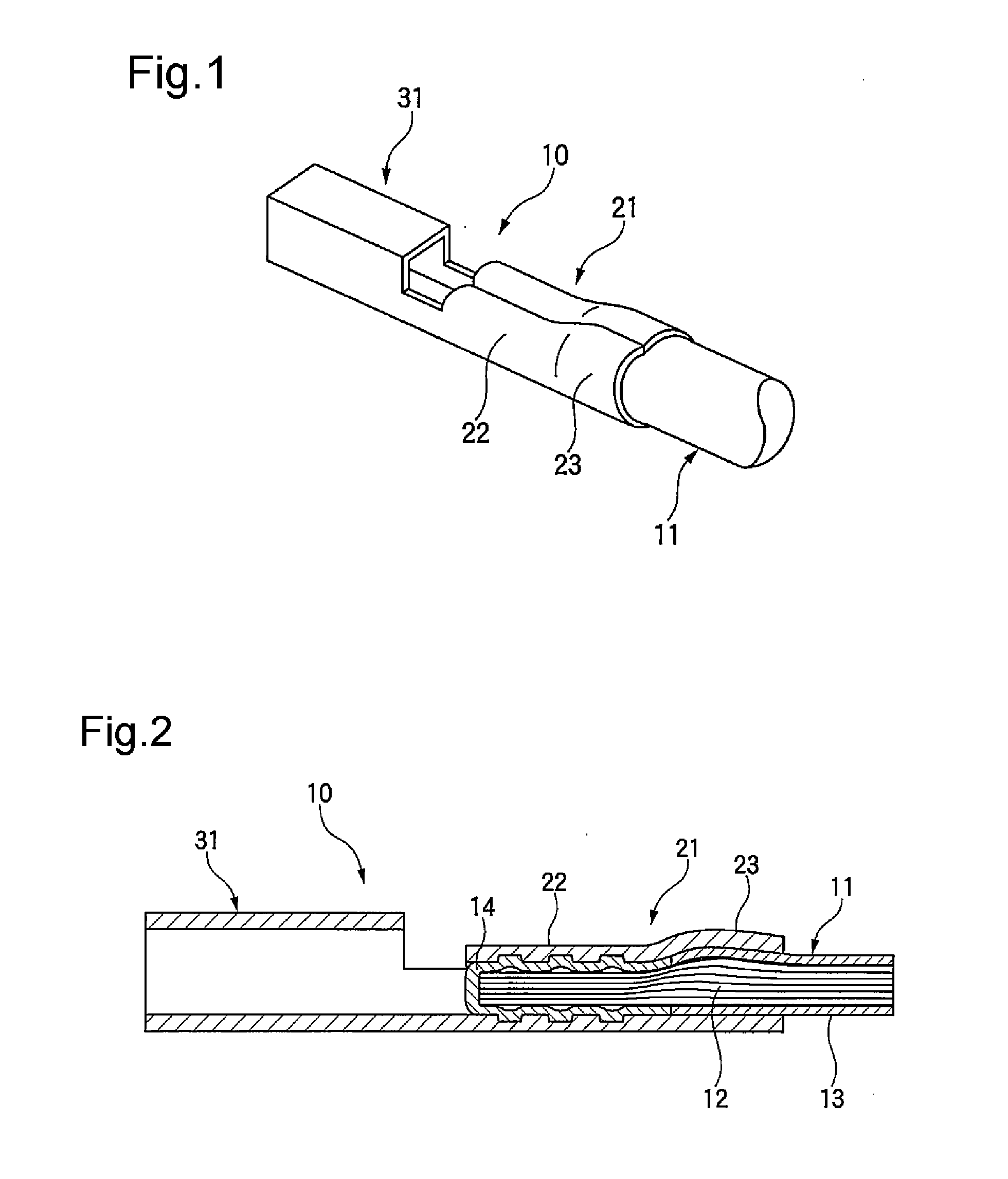
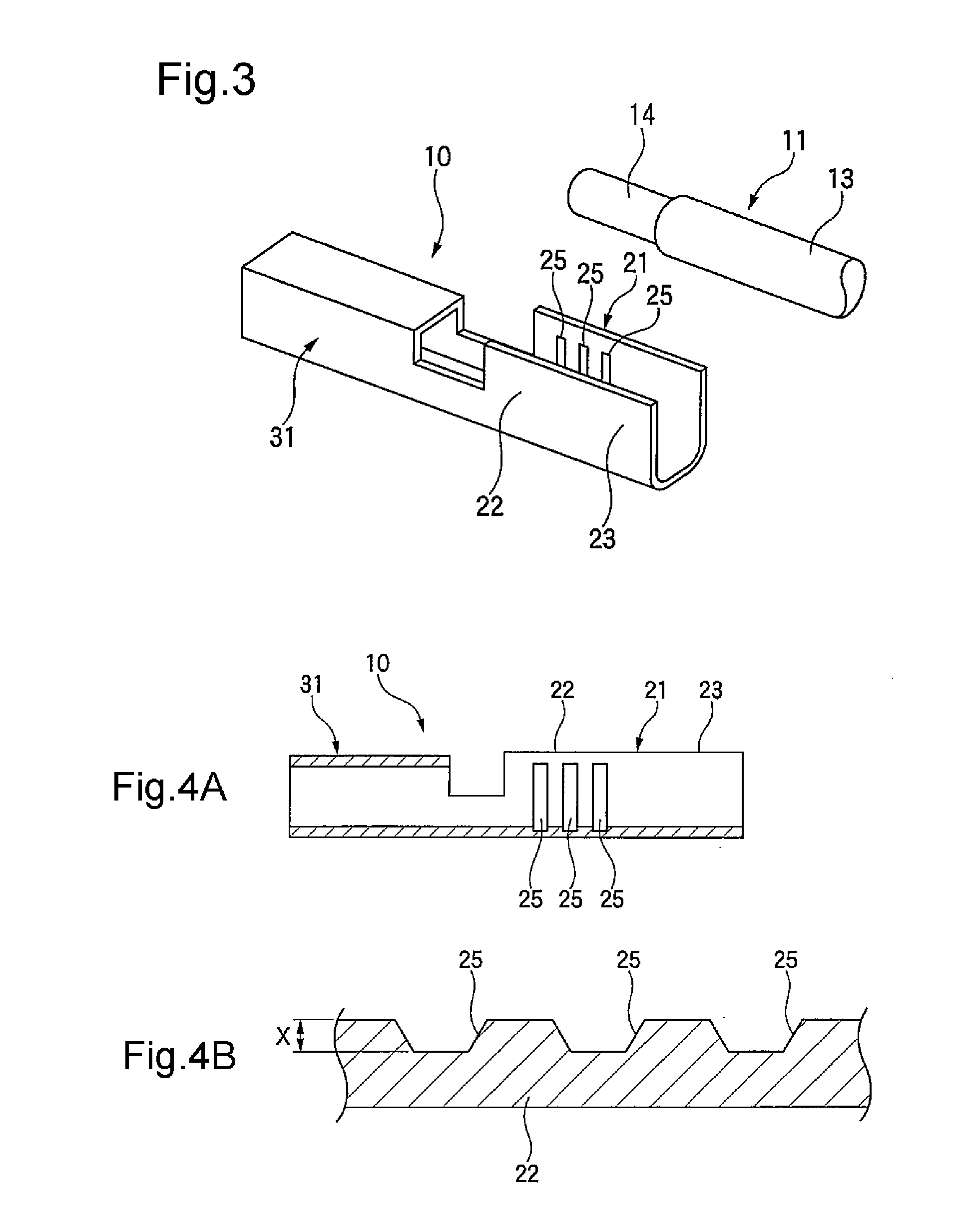
[0031]FIG. 1 is a perspective view showing a connector terminal of an embodiment of the invention; FIG. 2 is a cross section showing the connector terminal of the embodiment of the invention; FIG. 3 is an exploded perspective view showing the connector terminal of the embodiment of the invention; FIGS. 4A and 4B are illustrations showing the connector terminal, wherein FIG. 4A is a cross section of the entirety of the connector terminal and FIG. 4B is an enlarged cross section of a barrel portion; FIG. 5 is a side elevation of a portion of an end of an electric wire to which the connector terminal is to be connected when viewed in cross section; and FIG. 6 is a cross section of the barrel portion of the connector terminal connected to the electric wire.

[0032]As shown in FIGS. 1 through 3, a connector terminal 10 is connected to an electric wire 11. The electric wire 11 has a core wire ...


PUM


Abstract

In a connector terminal connected to an electric wire in which a conductor is covered with an outer cover, the terminal includes a barrel portion that is exposed from the outer cover and is to be crimped to the conductor coated with a covering, and an electrical connection portion electrically connected to a mating terminal, wherein a trench or a projection that is provided along a direction perpendicular to an axis of the electric wire are formed in an inner surface of the barrel portion, and a depth of the trench or a projecting dimension of the projection is made smaller than a covering thickness of the covering.

Description

CROSS REFERENCE TO RELATED APPLICATIONS[0001]This application is a continuation of PCT application No. PCT / JP2012 / 079720, which was filed on Nov. 9, 2012 based on Japanese Patent Application (No. 2011-247619) filed on Nov. 11, 2011, the contents of which are incorporated herein by reference.BACKGROUND OF THE INVENTION[0002]1. Field of the Invention[0003]The invention relates to a connector terminal connected to a terminal of an electric wire.[0004]2. Description of the Related Art[0005]In order to protect a connection portion of a connector terminal that is to be connected to a terminal of an electric wire, a hitherto known technique is to secure, within a molding die assembly including an upper die and a lower die, a hollow molding region into which a terminal connection portion made by crimping terminal hardware to a forefront conductor of a covered electric wire is to be set and accommodated. A molten molding resin is injected into the molding region, thereby covering and molding...

Claims


Application Information

Patent Timeline
IPC IPC(8): H01R4/20
CPCH01R4/206H01R4/184H01R4/188H01R4/20
Inventor SATO, KEI
Owner YAZAKI CORP
Why Eureka
Eureka Blog
Learn More