
Ultrasonic osteotome

a technology of ultrasonic and osteotome, which is applied in the field of ultrasonic osteotome, can solve the problems of difficult to precisely control the osteotome, uncomfortable patients, and inconvenient patients, and achieve the effect of easy control of the insertion angle of the osteotom

Inactive Publication Date: 2014-04-17
SUNNYTEC ELECTRONICS CO LTD
View PDF5 Cites 3 Cited by
  • Summary
  • Abstract
  • Description
  • Claims
  • Application Information

AI Technical Summary

Benefits of technology

The present invention is an osteotome that can be used to cut bone in the oral cavity of patients with smaller faces. It is designed to be inserted into the patient's mouth at a specific angle to facilitate precise cutting. The invention's unique design allows it to reach the desired cutting area without interfering with the patient's tongue or lips. This makes the procedure safer and easier for dental professionals.

Problems solved by technology

The conventional osteotomes are designed for western people who have larger face so that the conventional osteotomes are not suitable for the patients who have smaller face.
For the patients having smaller face, the osteotome is difficult to control precisely during operation when cutting the mandible.
Because the conventional osteotomes C1, C2 are designed not for the patients with smaller face or smaller oral cavity, the conventional osteotomes C1, C2 may contact the cheeks of the patients to result in uncomfortable to the patients.
When the oral cavity of the patients is small, the insertion angle for operating the conventional osteotomes C1, C2 is difficult to control.
Consequently, the desired cutting area of the mandible is not precisely cut.
Consequently, the use of the conventional osteotomes C1, C2 are inconvenient for the patients having smaller face or smaller oral cavity, including removal of wisdom teeth or bone transplant.

Method used


Image

  • Ultrasonic osteotome
  • Ultrasonic osteotome
  • Ultrasonic osteotome

Examples


Embodiment Construction

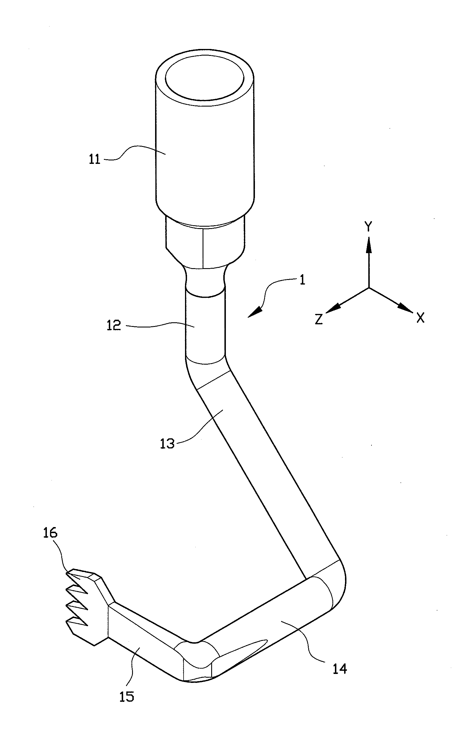
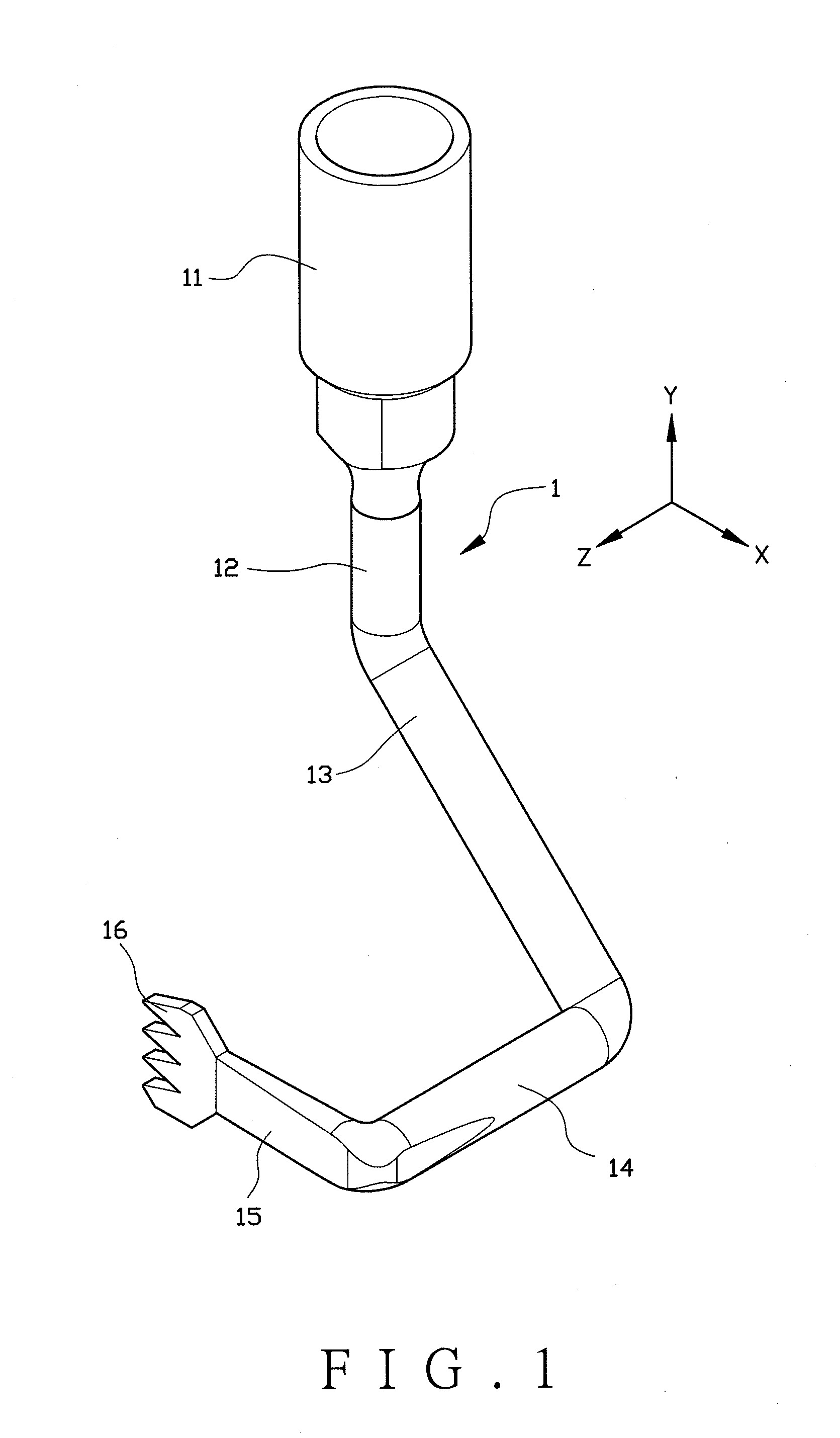
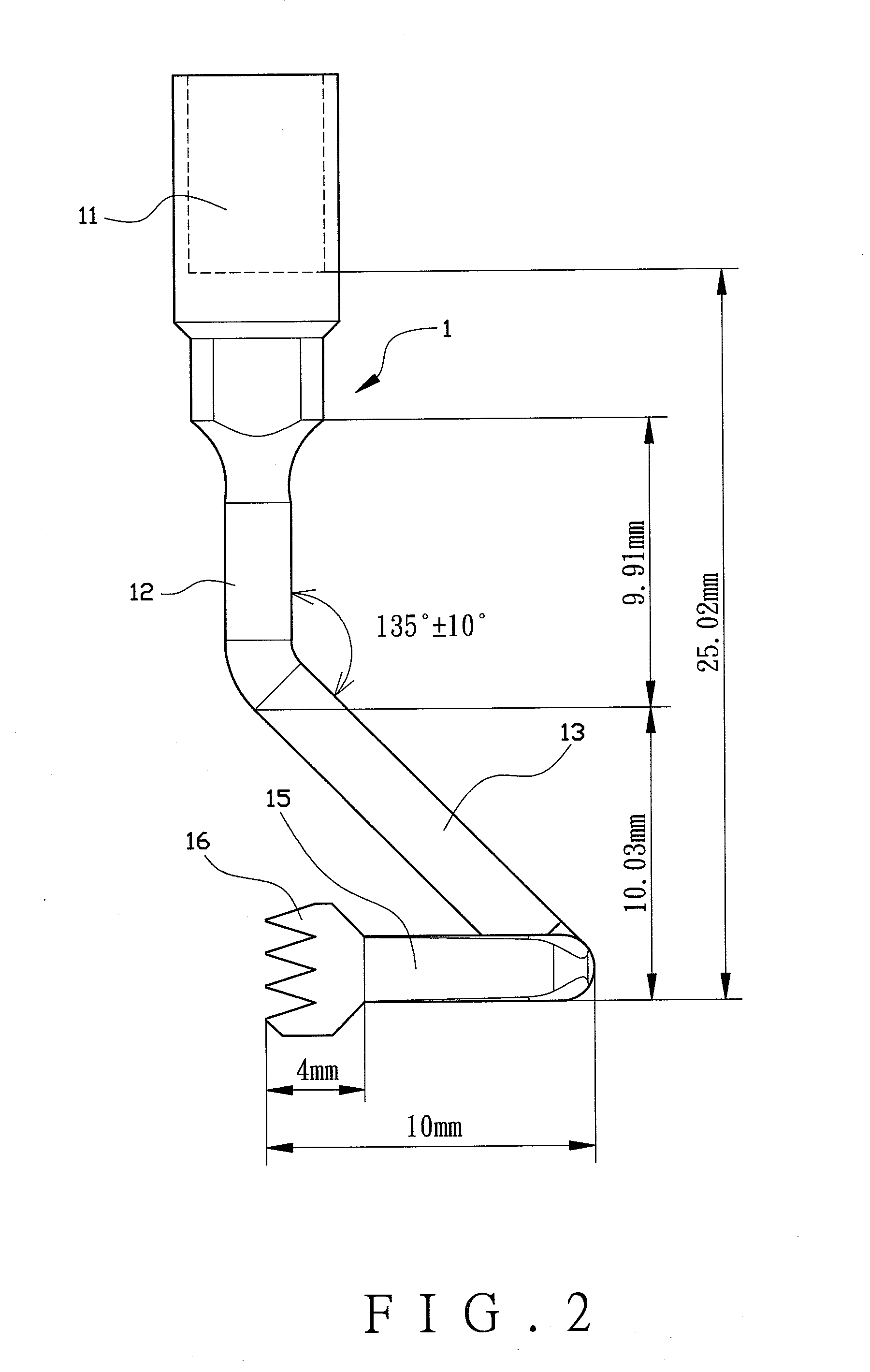
[0030]Referring to FIGS. 1 to 3, a preferred embodiment of the ultrasonic osteotome 1 of the present invention comprises a connector 11, a first arm 12, a second arm 13, a third arm 14, a fourth arm 15 and a cutting head 16. A coordinate system comprises an X axis, a Y axis and a Z axis, wherein the X axis, the Y axis and the Z axis are perpendicular to each other and intersect at an original point. The connector 11 extends along the Y axis. The first arm 12 extends along the Y axis and is connected to the second arm 13. The second arm extends along the plane with the X and Y axes. An angle between the first and second arms 12, 13 is within the range between 125 to 145 degrees, preferably is 135 degrees. The third arm 14 extends along the Z axis and is connected to the second arm 13 and the fourth arm 15. Wherein, the second arm extends toward positive direction of the X axis to connect with the first arm. The fourth arm 15 extends along the negative direction of the X axis and is c...


PUM


Abstract

An osteotome includes a connector, a first arm, a second arm, a third arm, a fourth arm and a cutting head. A coordinate system has an X axis, a Y axis, and a Z axis. The X axis, the Y axis and the Z axis are perpendicular to each other and intersect at an original point. The connector extends along the Y axis. The first arm, extending along the Y axis, connects to the second arm, extending along the plane with the X and Y axes. An angle between the first and second arms is within a range between 125 to 145 degrees. The third and fourth arms respectively extend along the Z axis and the X axis. The cutting head is parallel to the X axis and the Y axis so as to easily control the insertion angle of the osteotome for the patients with smaller face or smaller oral cavity.

Description

FIELD OF THE INVENTION[0001]The present invention relates to an ultrasonic osteotome, also called as the ultrasonic bone knife or ultrasonic surgical knife, and more particularly, to an ultrasonic osteotome for patients having smaller oral cavity or smaller face, and the insertion angle of the ultrasonic osteotome is easily controlled.BACKGROUND OF THE INVENTION[0002]The osteotome is used to cut dentine and enamel while the soft tissues are protected.[0003]The conventional osteotomes are designed for western people who have larger face so that the conventional osteotomes are not suitable for the patients who have smaller face. For the patients having smaller face, the osteotome is difficult to control precisely during operation when cutting the mandible.[0004]FIGS. 9 and 10 respectively show the first and second conventional osteotomes C1 and C2. Because the conventional osteotomes C1, C2 are designed not for the patients with smaller face or smaller oral cavity, the conventional os...

Claims


Application Information

Patent Timeline
IPC IPC(8): A61B17/16
CPCA61B17/1673A61B2017/00738A61C1/07A61C3/02A61C3/12A61B2017/320077
Inventor LIN, CHUN-PINCHANG, HAO-HUNGHUANG, YI-CHAOCHIANG, YU-CHIHCHEN, HANN-KUANGLEE, CHAO-PING
Owner SUNNYTEC ELECTRONICS CO LTD
Learn More