Supercharge Your Innovation With Domain-Expert AI Agents!

Deposition apparatus

a deposition apparatus and apparatus technology, applied in chemical vapor deposition coatings, coatings, electric discharge tubes, etc., can solve the problems of reducing the size of a semiconductor device, affecting and limiting the use of existing deposition methods, so as to improve the stability of the deposition apparatus and improve the accuracy of the process. , the effect of reducing the resistance caused by the plasma connection terminal

Inactive Publication Date: 2014-04-24
ASM IP HLDG BV
View PDF11 Cites 3 Cited by
  • Summary
  • Abstract
  • Description
  • Claims
  • Application Information

AI Technical Summary

Benefits of technology

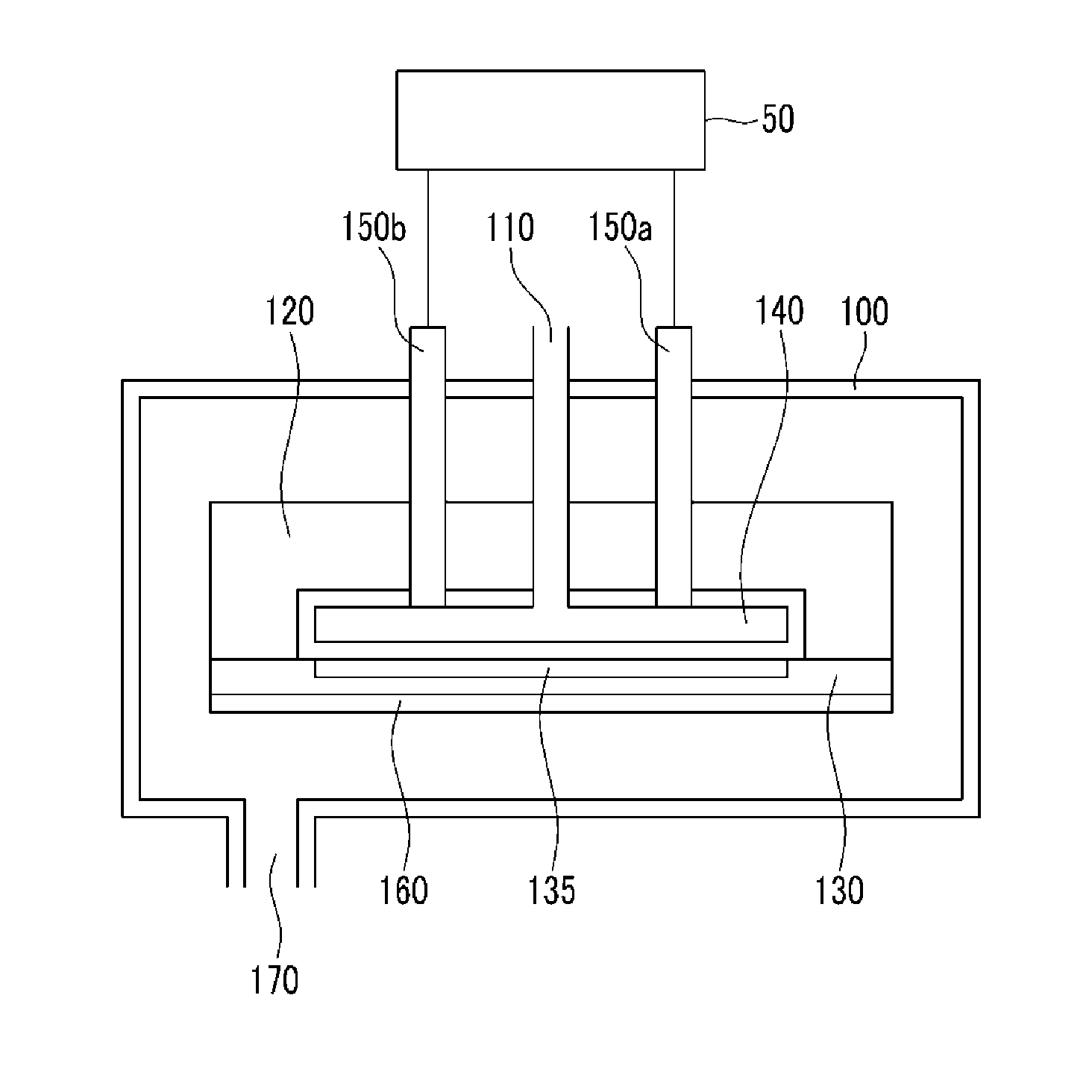
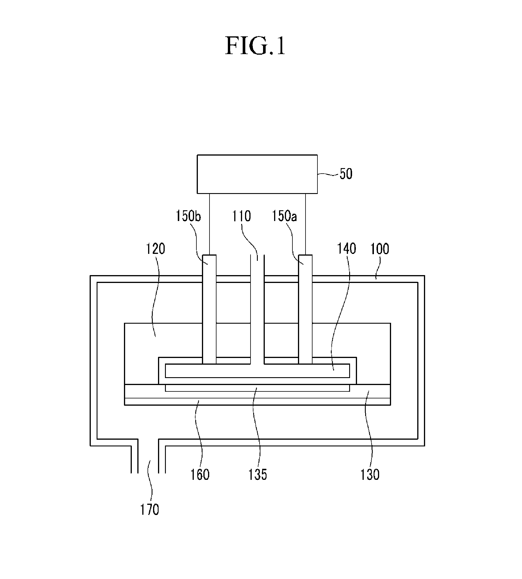
The present invention provides a deposition apparatus that can stably supply plasma and enhance the stability and accuracy of a process. This is achieved by preventing oxidization of the plasma connection terminal, even when high RF power is provided, which reduces resistance and allows for a distributed current, improving plasma supply and stability.

Problems solved by technology

However, as the size of a semiconductor device becomes smaller, existing deposition methods showed limitation.
In the plasma enhanced ALD method, when a plasma is supplied to a reaction gas that is difficult to react in the conventional thermal atomic layer deposition method, a reaction can be easily induced so that films having various qualities can be deposited although such a process would be difficult to achieve in the conventional thermal ALD method.
When such a process is repeated, overheating of an RF rod occurs.
Therefore, overheating of the RF rod results in reduced accuracy of the process and affects stability of the deposition apparatus.
Further, in a process in which high RF power is necessary, as RF power increases, high current flows at the RF rod and at a connection portion positioned between the RF rod and the plasma electrode, and thus, the RF rod and the connection portion may be oxidized.

Method used


Image

  • Deposition apparatus
  • Deposition apparatus
  • Deposition apparatus

Examples


Embodiment Construction

[0023]The present invention will be described more fully hereinafter with reference to the accompanying drawings, in which exemplary embodiments of the invention are shown. As those skilled in the art would realize, the described embodiments may be modified in various different ways, all without departing from the spirit or scope of the present invention.

[0024]In the drawings, the thickness of layers, films, panels, regions, etc., are exaggerated for clarity. Like reference numerals designate like elements throughout the specification. It will be understood that when an element such as a layer, film, region, or substrate is referred to as being “on” another element, it can be directly on the other element or intervening elements may also be present. In contrast, when an element is referred to as being “directly on” another element, there are no intervening elements present.

[0025]Hereinafter, a deposition apparatus according to an exemplary embodiment of the present invention will be...


PUM

PropertyMeasurementUnit
plasma poweraaaaaaaaaa
resistanceaaaaaaaaaa
sizeaaaaaaaaaa

Abstract

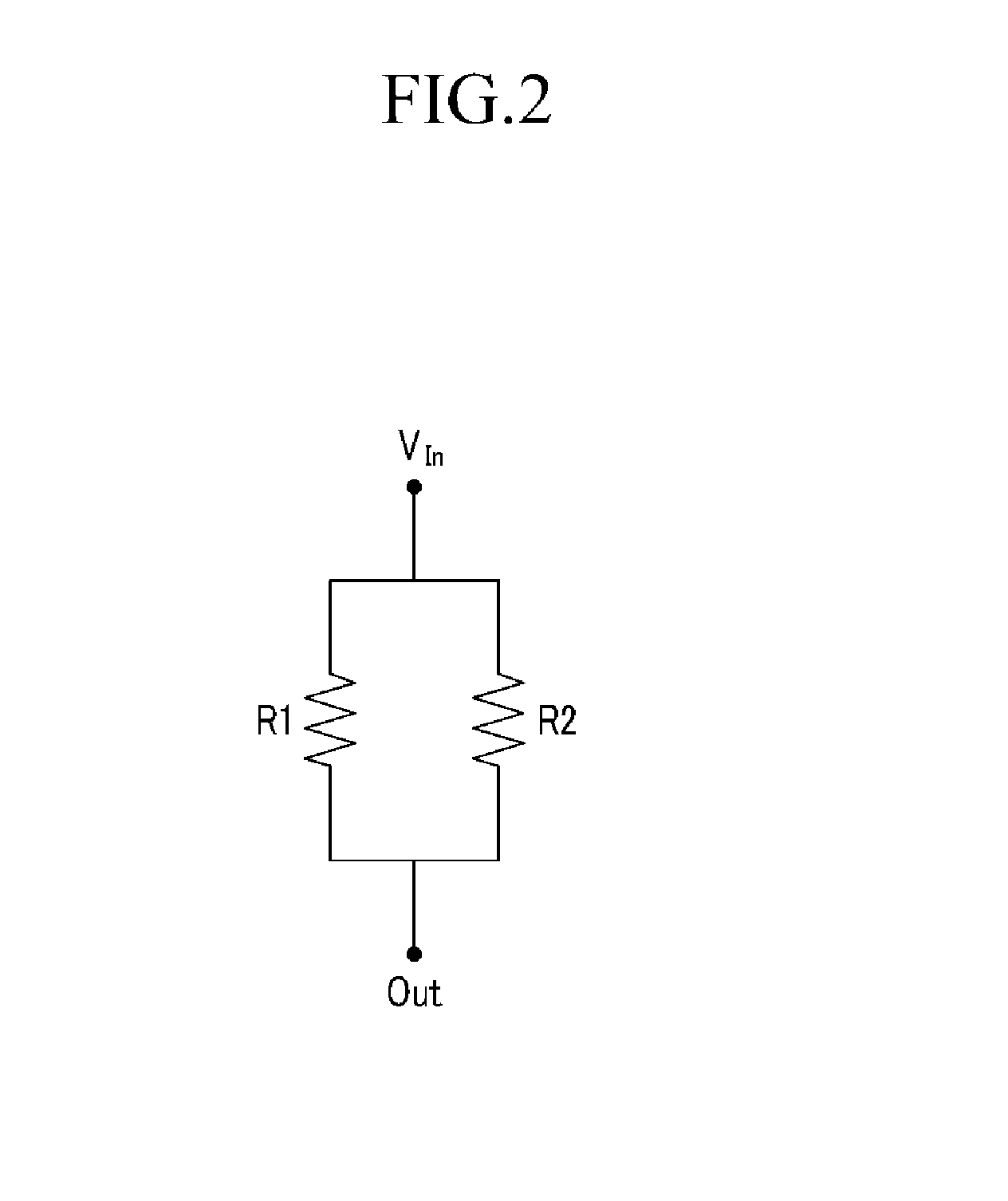
In a deposition apparatus, as a plurality of plasma connection terminals that transfer plasma power to a plasma electrode are coupled in parallel to the plasma electrode, resistance caused by the plurality of plasma connection terminals is reduced and a current is distributed such that heat generated in the plurality of plasma connection terminals can be distributed. Therefore, even if high RF power is used, by preventing the plurality of plasma connection terminals from being oxidized, plasma is stably supplied and thus, stability of a deposition apparatus and the accuracy of a process can be enhanced.

Description

CROSS-REFERENCE TO RELATED APPLICATION[0001]This application claims priority to and the benefit of Korean Patent Application No. 10-2012-0118062 filed in the Korean Intellectual Property Office on Oct. 23, 2012, the entire contents of which are incorporated herein by reference.BACKGROUND OF THE INVENTION[0002](a) Field of the Invention[0003]The present invention relates to a deposition apparatus.[0004](b) Description of the Related Art[0005]As a method of depositing a thin film on a silicon substrate, a physical vapor deposition (PVD) method and a chemical vapor deposition (CVD) method have been used.[0006]However, as the size of a semiconductor device becomes smaller, existing deposition methods showed limitation. As a next generation deposition method to replace the existing deposition method, an atomic layer deposition (ALD) method has been developed and the ALD method is currently widely used.[0007]In the ALD method, a thin film is deposited on a substrate by a self-limiting pro...

Claims


Application Information

Patent Timeline
Patent Type & Authority Applications(United States)
IPC IPC(8): C23C16/452
CPCC23C16/452C23C16/509H01J37/32577H01J37/32082
Inventor KIM, KI JONGKIM, DAE YOUNJANG, HYUN SOO
Owner ASM IP HLDG BV
Features
  • R&D
  • Intellectual Property
  • Life Sciences
  • Materials
  • Tech Scout
  • Unparalleled Data Quality
  • Higher Quality Content
  • 60% Fewer Hallucinations
Learn More