Bolt Guide Device for a Floating Caliper Disc Brake and Corresponding Floating Caliper Disc Brake

Active Publication Date: 2014-04-24
LUCAS AUTOMOTIVE GMBH
View PDF5 Cites 3 Cited by
  • Summary
  • Abstract
  • Description
  • Claims
  • Application Information

AI Technical Summary

Benefits of technology

The present invention provides a bolt guiding device for a floating caliper disc brake that effectively combats the problem of high breakaway torsets while being simple and economical. The invention also provides a slide bush with at least one recess or indentation for receiving lubricants to prevent the disadvantageous effect of high retaining forces caused by static friction and ensure easy actuation even in the event of prolonged stoppages. The slide bush also has at least one radial groove that provides a further grease reservoir and improves long-term lubricating capability. The transition between the radial groove and other surfaces is conical or rounded to ensure improved sliding behavior and facilitate movement between the sliding surface and guiding surfaces.

Problems solved by technology

After the static friction has been overcome, these relatively high actuating forces however lead to an unexpectedly strong braking effect.
The driver may find this disturbing.
This solution similarly has the drawback of relatively large guiding surfaces which, if a vehicle has not been used for a prolonged period, then leads to the previously described high breakaway torques with the disadvantageous effect of unexpectedly strong braking effects.
This solution also leads to relatively high static friction forces that entail the described disadvantageous effect of high breakaway torques.
In these documents use is made i.a. of multipart guide bodies or guide bodies in the form of spring elements, which because of their complexity lead to arrangements that are relatively cost-intensive and hence rather less attractive for mass production.

Method used


Image

  • Bolt Guide Device for a Floating Caliper Disc Brake and Corresponding Floating Caliper Disc Brake
  • Bolt Guide Device for a Floating Caliper Disc Brake and Corresponding Floating Caliper Disc Brake
  • Bolt Guide Device for a Floating Caliper Disc Brake and Corresponding Floating Caliper Disc Brake

Examples


Embodiment Construction

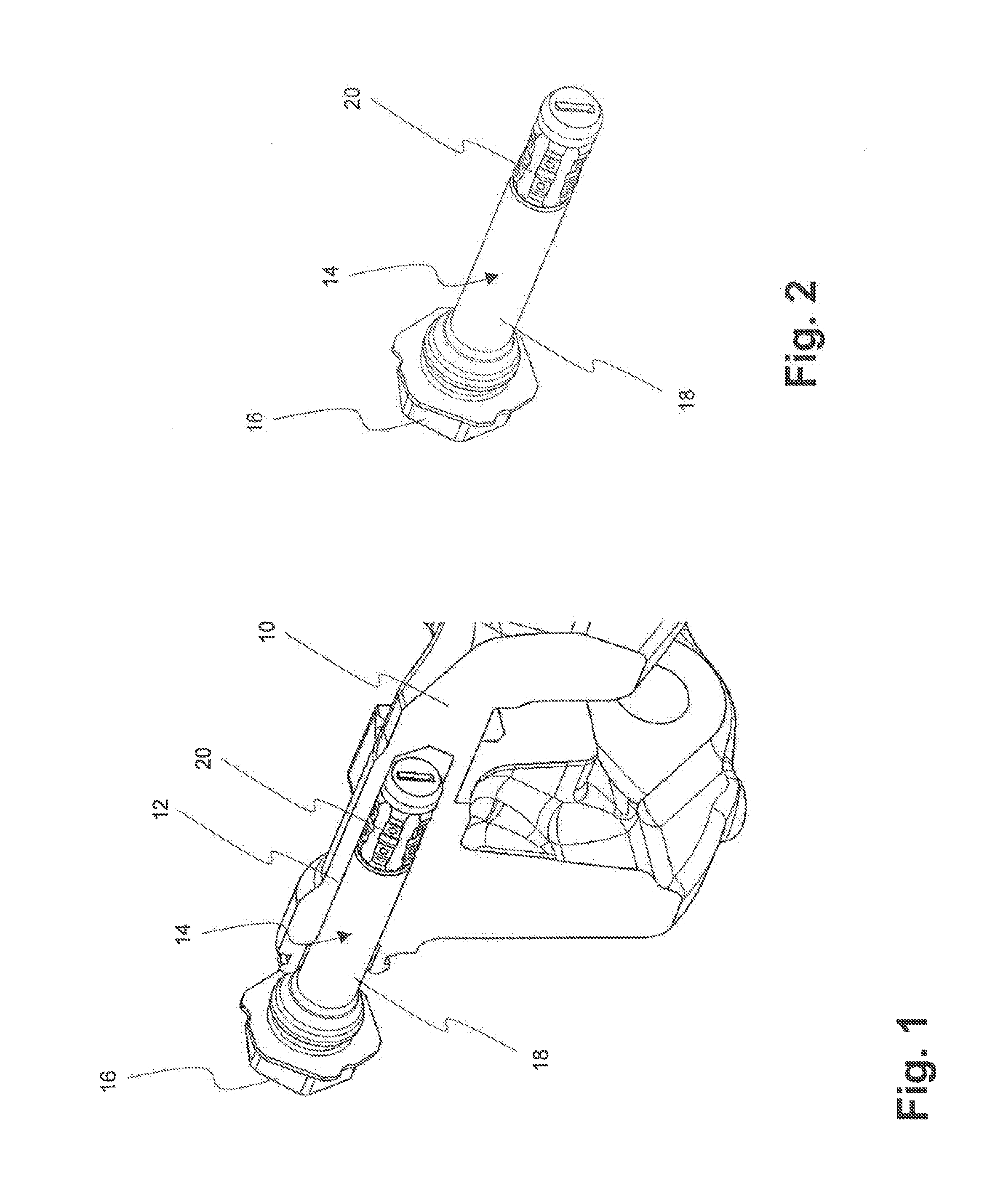
[0026]In FIG. 1 a brake carrier of a floating caliper brake is shown in a part-sectional view and generally denoted by 10. It comprises a location hole 12. Accommodated in the location hole 12 is a guide bolt 14, which at its in FIG. 1 Left—end has a bolt head 16, by which it is fixed to a non-illustrated brake caliper. A shank portion 18 of the guide bolt 14 projects into the location hole 12. Close to its free end the locating bolt 14 is provided with a portion, in which a slide bush 20 is accommodated. The guide bolt 14 is represented once again as a single component in an, as it were, cut-free manner in FIG. 2.

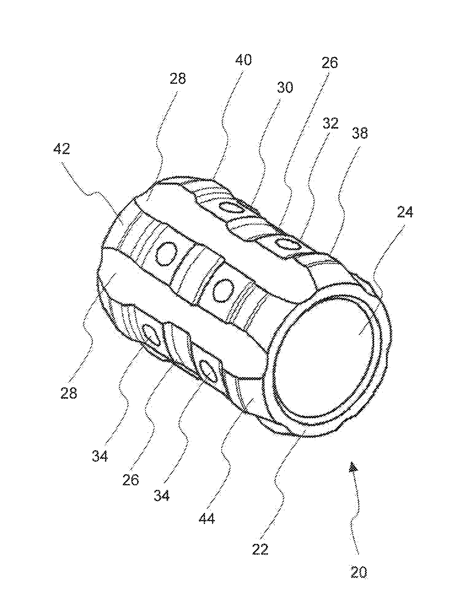
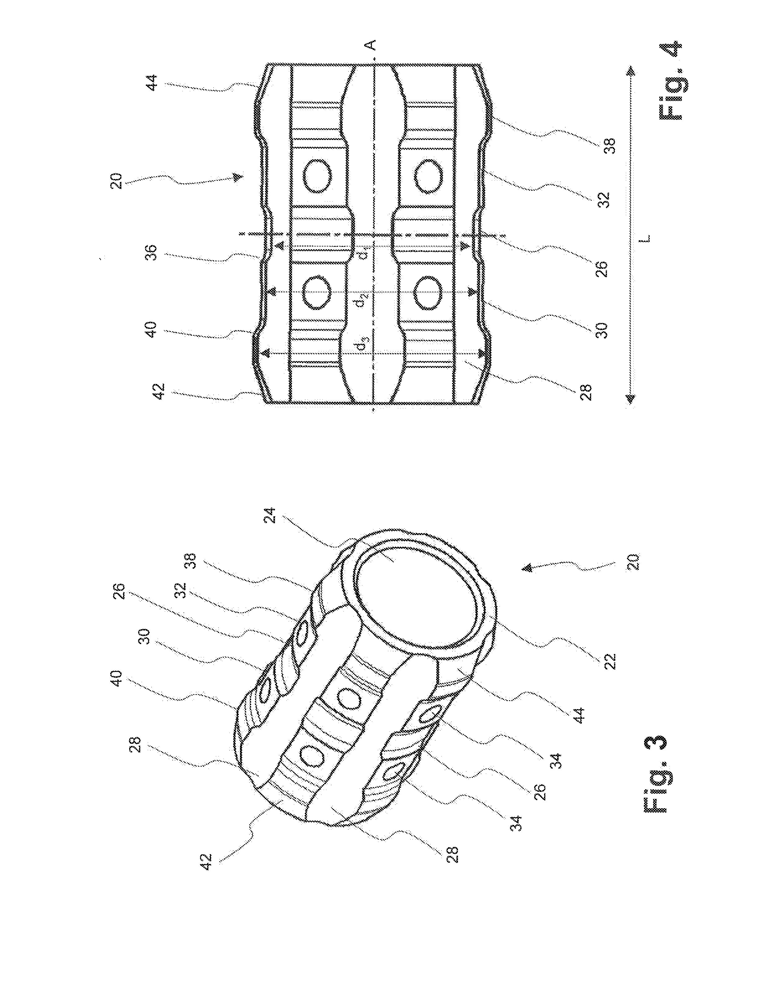
[0027]In FIG. 3 the guide bush 20 may be seen in a perspective single component drawing, while being shown in side view in FIG. 4. In FIGS. 3 and 4 it may be seen that the slide bush 20 is manufactured from a tubular plastic body 22 that has a central opening 24, by means of which it may be slipped onto a portion of reduced diameter of the guide bolt 14. The slide bush 20 ...


PUM


Abstract

A bolt guiding device for a floating caliper disc brake, having at least one guide bolt that is supported in a brake carrier and mounted on a brake caliper, wherein the brake caliper is movably guided over the guide bolt in the axial direction thereof. The bolt guiding device comprises a slide bush, wherein one surface of the inner circumferential surface and outer circumferential surface acts as a retaining surface on which the slide bush is retained, and wherein the other surface of the inner circumferential surface and outer circumferential surface acts as a sliding surface on which the slide bush slides. For this purpose, the slide bush has, facing the sliding surface, at least one guiding surface on each side of the centre of the slide bush and at least one intermediate surface extending in the circumferential direction on each side of the centre of the slide bush, wherein the diameter of the at least one guiding surface is dimensioned in such a way that said guiding surface is in close contact with the sliding surface, and wherein the diameter of the intermediate surface is dimensioned in such a way that said intermediate surface is provided in direct contact with or with a slight radial spacing from the sliding surface.

Description

CROSS-REFERENCE TO RELATED APPLICATIONS[0001]This application is a national stage of International Application No. PCT / EP2012 / 001527 filed Apr. 5, 2012, the disclosures of which are incorporated herein by reference in entirety, and which claimed priority to German Patent Application No. DE 10 2011 017 220.3 filed Apr. 15, 2011, the disclosures of which are incorporated herein by reference in entirety.BACKGROUND OF THE INVENTION[0002]The present invention relates to a bolt guiding device for a floating caliper disc brake, having at least one guide bolt that is supported in a brake carrier and mounted on a brake caliper, wherein the brake caliper is movably guided over the guide bolt in the axial direction thereof, wherein the bolt guiding device is disposed between an inner circumferential surface of a location hole of the brake carrier and an outer circumferential surface of the guide bolt accommodated therein, wherein the bolt guiding device comprises a slide bush, wherein one surf...

Claims


Application Information

Patent Timeline
IPC IPC(8): F16D55/2265
CPCF16D55/2265F16D55/22655F16D55/227
Inventor BECKER, MARCOZENZEN, GUIDODANG, NONGHEES, DIRKBRAND, GEORGDEBUS, DIRK
Owner LUCAS AUTOMOTIVE GMBH
Why Eureka
Try Eureka