Cover with handle structure for facilitating hold a device and method of using the same

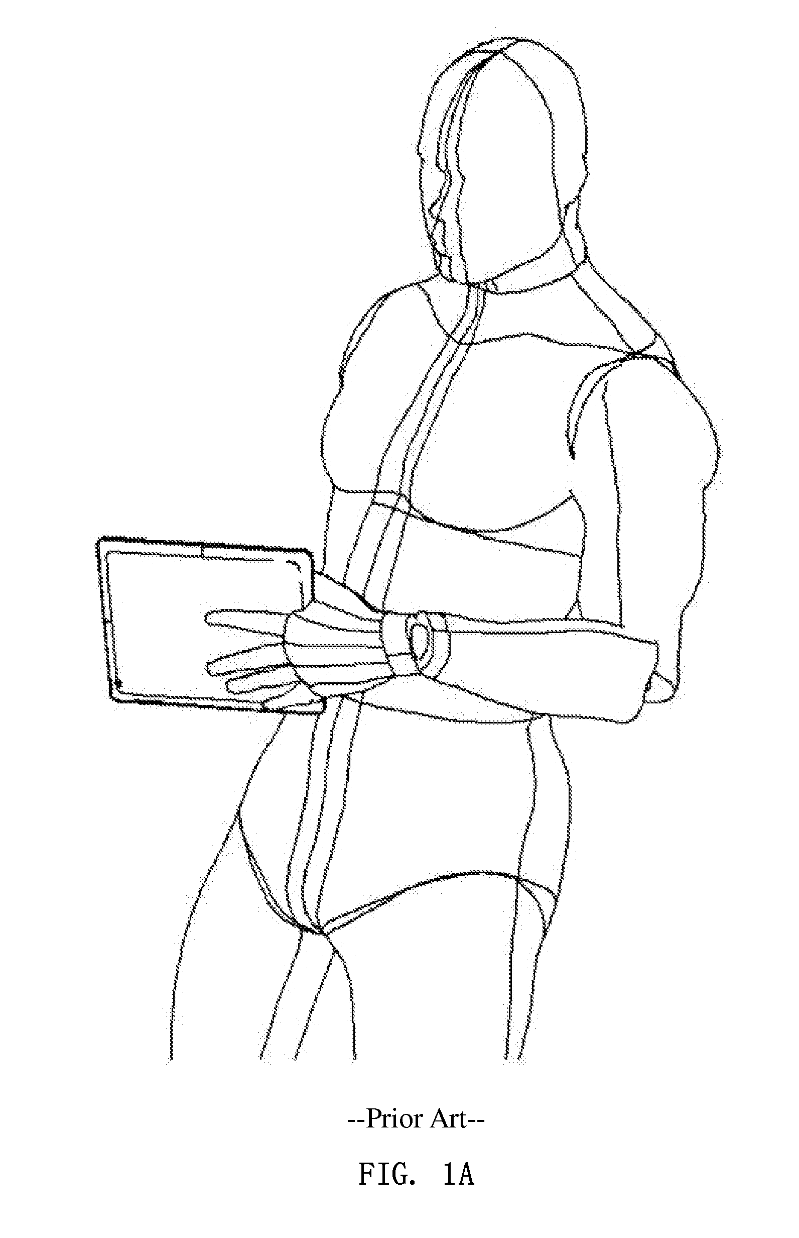
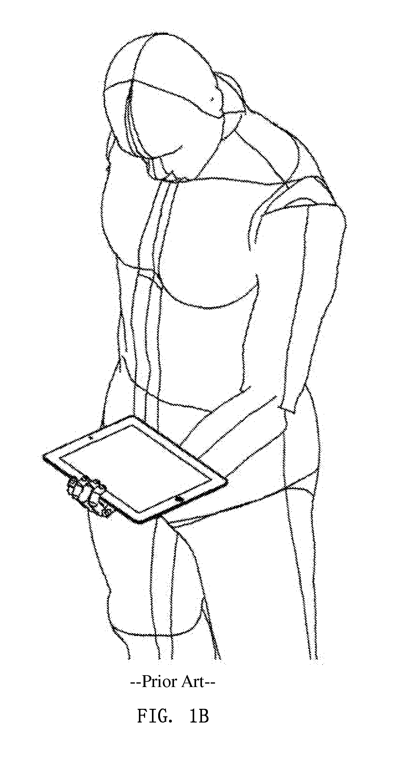
a technology of handle structure and cover, which is applied in the field of covers, can solve the problems of not being considered compact and lightweight as a whole, user's additional force to hold the device firmly, and the way in fig. 1a is not lasting, so as to reduce physical injury or fatigue

Inactive Publication Date: 2014-04-24
CHEN JEN TE
View PDF1 Cites 4 Cited by
  • Summary
  • Abstract
  • Description
  • Claims
  • Application Information

AI Technical Summary

Benefits of technology

[0010]In order to satisfy the need that has not been truly satisfied and solve the problems of the prior art, an objective of the present invention is to provide a cover having a handle structure for facilitating a user to firmly hold a device which has a plurality of faces, capable of being held as the position of a palm of the user is moved close to the center of the device, and thus reducing physical injury or fatigue while operating.

Problems solved by technology

The way in FIG. 1A is not a lasting grasp because of the weight of the device and the torque it produced.
The way in FIG. 1B is not comfortable and ergonomic because the outer frame is not designed for matching various holding angles, thus a user has to provide additional force to hold the device firmly.
Even though the handle can be folded, such a design is still not considered compact and lightweight as a whole.
A problem is the necessity of ensuring whether the belt is securely fixed while using.
If the belt is replaced by an elastic belt, then the problem will be the reduction of elasticity of the elastic belt.
The major problem is that the additional structure may affect usability of other functions and looks bulky.
Moreover, its sense of designation is usually not coherent with the sense of technological electronic products.
Though the external structure is foldable and occupies no space, it cannot function as a cover, and provide only one grippable position that cannot support the device in both portrait and landscape orientations.
However it does not have a handle structure for facilitating a user to hold the device firmly.

Method used


Image

  • Cover with handle structure for facilitating hold a device and method of using the same
  • Cover with handle structure for facilitating hold a device and method of using the same
  • Cover with handle structure for facilitating hold a device and method of using the same

Examples


first embodiment

[0044]The ridgeable portion disclosed in the first embodiment further has an opening located on the one part 78 of the ridgeable portion. The opening is provided by forming an opening cut line 70, and thus an openable cap 72 is formed and a hinged portion 71 of the openable cap is conneceted to the ridgeable portion. As FIG. 5 shows, the opening is provided for inserting fingers 103, 104 to facilitate hold. Trough the opening to hold the cover 4, the user's palm can also be moved close to the center of the device 1 to facilitate hold. If the opening cut line 70 extends to include the hinged portion 71 of the openable cap, the openable cap can be omitted and an opening is left there. Such a configuration can also be held as the way shown in FIG. 5, but less protective area can be provided by the cover 4 because the openable cap 72 is removed.

[0045]The present invention further has limiting elements set. One of the limiting elements is located on the at least one disconnected portion ...

second embodiment

[0046]the present invention demonstrates another workable assembly method of the first joint 5 and a design of the cover. As FIG. 6 and FIG. 7 show, according to the present invention the cover 4 is rotatably connected to a protective shell 55 for a tablet computer. Through a protective shell fixing means, a front face 552 of the protective shell 55 is attached to the tablet computer (not shown), and the protective shell 55 is fixed on the tablet computer. In practical use, a back face 553 of the protective shell is equivalent to the second face of the device. The protective shell fixing means in the drawing is to utilize the edges 556 of the four corners of the protective shell to seize the outer frame of the tablet computer after the protective shell is combined with the tablet computer.

[0047]The first joint 5 of the embodiment in the drawing is the same as the above mentioned double hinged structure. Furthermore, a enhanced area 85 with hard lining material can be integrated into...

third embodiment

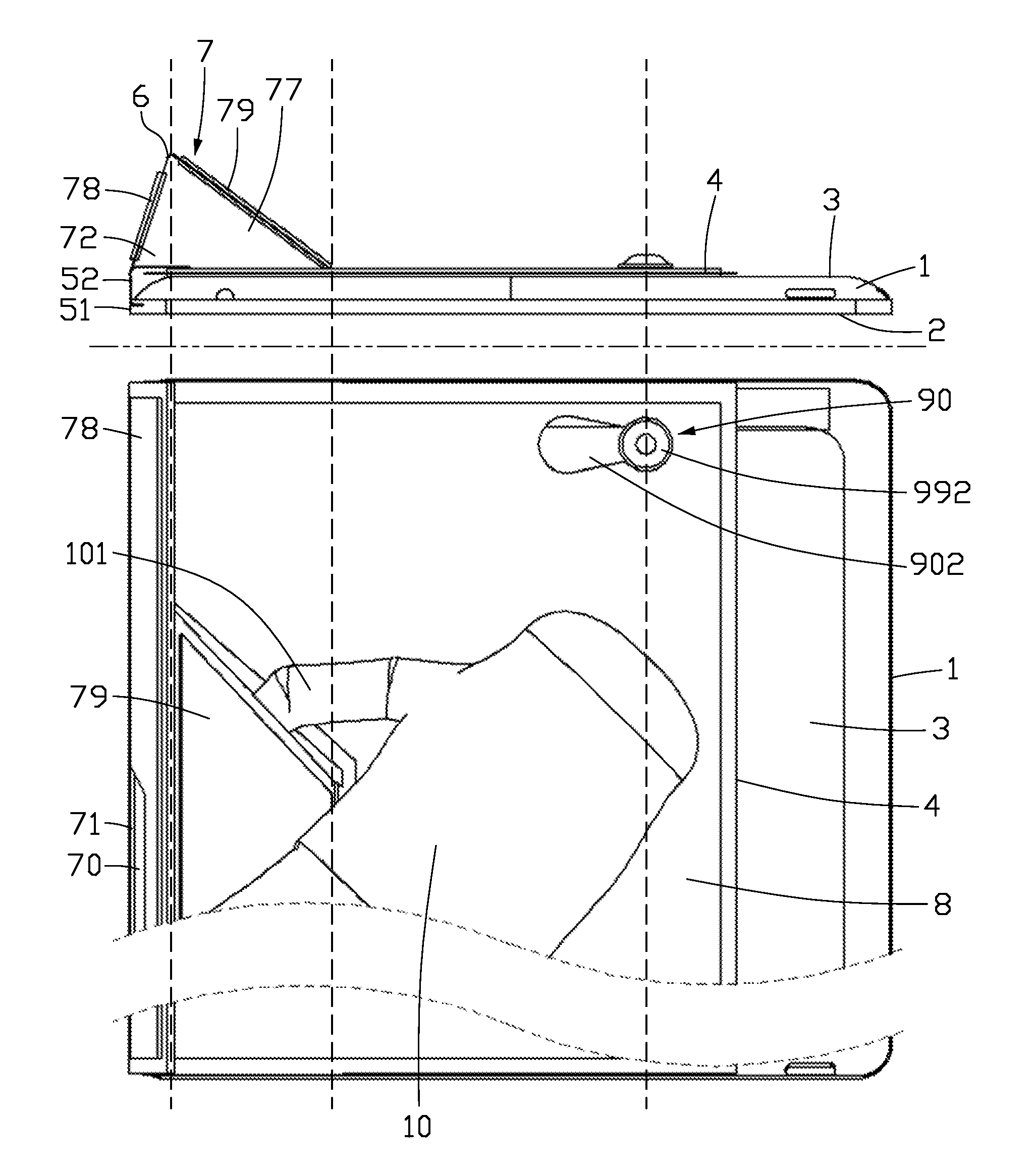
[0056]The third embodiment is used hereinafter for describing others using methods of the cover of the present invention. Coinciding with the spirit of the present invention with appropriate conditions, the other using methods can also be implemented on various practical embodiments. As FIG. 8 shows, while the cover 4 is ridged from the second face 3 of the device 1, a handle portion 79 is formed for inserting at least one finger (a left hand's thumb 101) from a side thereof into the space formed inside the second joint 6, in cooperation with the palm 10 to support the device 1 to facilitate hold the device 1. Since the finger is retained in the tubular space, user can cope with sudden external forces, and thus avoiding dropping the device 1. Moreover, the area between the thumb and the index finger can touch against the edge of the handle portion 79, which makes hold more firmly.

[0057]Due to the weight of the device 1, when the device is held close to perpendicular, the friction fo...


PUM


Abstract

A cover with structure for facilitating hold a device enables a user to hold the device with plurality of faces stably. It can be configured to ridge a ridgeable portion and form a tubular space. The user can retain at least one finger in the space to hold the cover such that his palm can be placed more close to the center of the device to facilitate hold the device.

Description

CROSS-REFERENCE TO RELATED APPLICATIONS[0001]This application claims priority based on Taiwan Patent Application Serial Number 100137811, filed on Oct. 19, 2011, the subject matter of which is incorporated herein by reference.FIELD OF THE INVENTION[0002]The present invention relates to a cover, and more particularly to a cover capable of forming a handle structure for facilitating a user to firmly hold a device with a plurality of faces.BACKGROUND OF THE INVENTION[0003]Portable devices are convenient to utilize their functions for users. But how to properly hold the portable devices while operating them, and avoiding accidentally dropping them, improving operating efficiency, and reducing operation injury and fatigue have become important subjects. Since post-PC era is coming and the tablet computers are getting popular, the subjects are more important than before.[0004]FIGS. 1A and 1B show two traditional ways of holding a tablet computer. The way in FIG. 1A is not a lasting grasp ...

Claims


Application Information

Patent Timeline
Patent Type & Authority Applications(United States)
IPC IPC(8): A45F5/00
CPCA45F5/00A45C11/00A45C2011/003A45F2005/008A45F2200/0525
Inventor CHEN, JEN-TE
Owner CHEN JEN TE
Why Eureka
Try Eureka