Inspection apparatus and inspection method
- Summary
- Abstract
- Description
- Claims
- Application Information
AI Technical Summary
Benefits of technology
Problems solved by technology
Method used
Image

Examples
Example
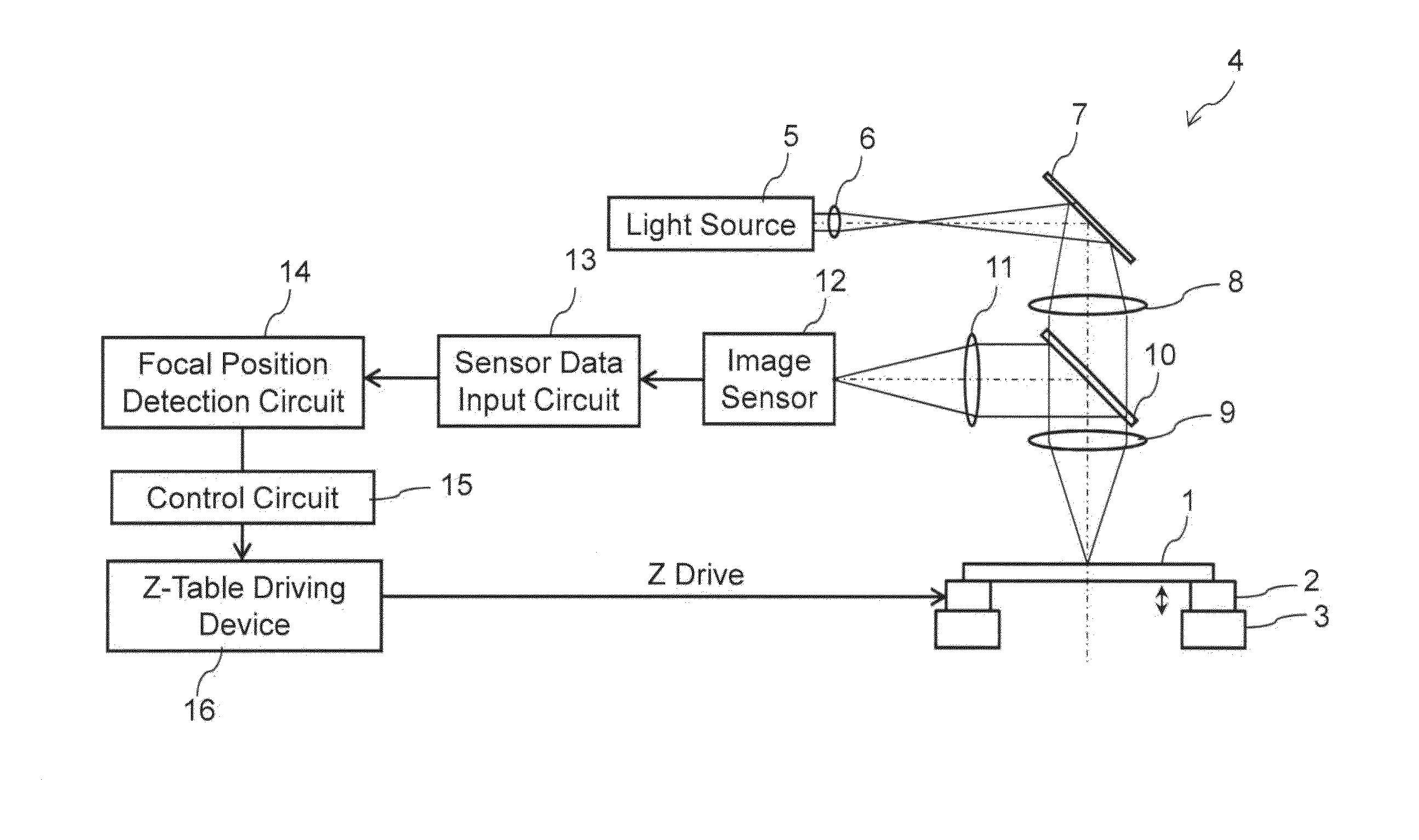
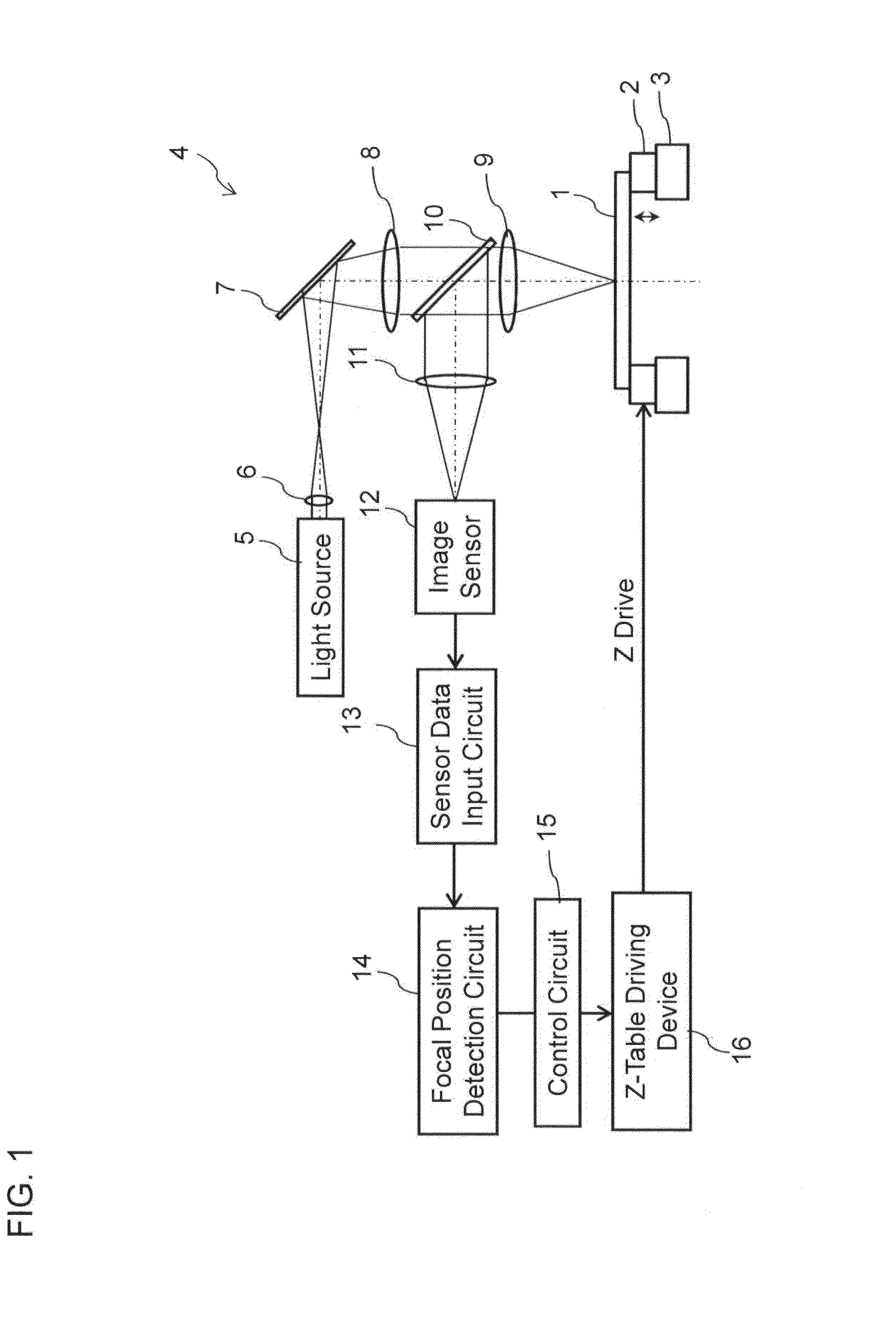
[0043]FIG. 1 is a view illustrating a configuration of a focal position detection apparatus according to a first embodiment.
[0044]Referring to FIG. 1, a sample 1 is placed on a Z-table 2 that is vertically movable. The Z-table 2 is also horizontally movable by an XY-table 3. The repetitive pattern such as the line and space pattern and a hole pattern, namely, the regular pattern having periodic repetition is formed in the sample 1. A master pattern and a daughter pattern, which are used in a nanoimprint technology, can be cited as an example of the sample 1.
[0045]Preferably the sample 1 is supported at three points by support members provided in the Z-table 2. In the case the sample 1 is supported at four points, it is necessary to accurately adjust a level with respect to the support member. When the level is insufficiently adjusted, there is a risk of deforming the sample 1. On the other hand, in the three-point support, the sample 1 can be supported while the deformation of the s...
Example
Second Embodiment
[0064]FIG. 6 is a view illustrating a configuration of a focal position detection apparatus according to a second embodiment.
[0065]Referring to FIG. 6, a sample 101 is placed on a Z-table 102 that is vertically movable. The Z-table 102 is also horizontally movable by an XY-table 103. The repetitive pattern such as the line and space pattern and the hole pattern, namely, the regular pattern having periodic repetition is formed in the sample 101. The master pattern and the daughter pattern, which are used in the nanoimprint technology, can be cited as an example of the sample 101.
[0066]Preferably the sample 101 is supported at three points by the support members provided in the Z-table 102. In the case that the sample 101 is supported at four points, it is necessary to accurately adjust the level with respect to the support member. When the level is insufficiently adjusted, there is a risk of deforming the sample 101. On the other hand, in the three-point support, the...
Example
Third Embodiment
[0081]FIG. 10 is a view illustrating a configuration of an inspection apparatus 100 according to a third embodiment. As illustrated in FIG. 10, the inspection apparatus 100 includes an optical image acquisition unit A and a controller B. In FIG. 10, the component identical to that in FIG. 1 is designated by the numeral identical to that in FIG. 1.
[0082]The optical image acquisition unit A includes an optical system, which is constructed by the light source 5, lenses 6, 8, 9, and 11′, the mirror 7, the image sensor 12, and the sensor data input circuit 13. The optical image acquisition unit A includes the vertically movable Z-table 2, the horizontally (an X-direction and a Y-direction) movable XY-table 3, a laser length measuring system 90, and an autoloader 130. The XY-table 3 may have a structure that is movable in a rotating direction (θ-direction).
[0083]The sample 1 that becomes an inspection target is placed on the Z-table 2. The Z-table 2 is provided on the XY-t...
PUM
 Abstract
Description
Claims
Application Information
 - R&D Engineer
- R&D Manager
- IP Professional
- Industry Leading Data Capabilities
- Powerful AI technology
- Patent DNA Extraction
Browse by: Latest US Patents, China's latest patents, Technical Efficacy Thesaurus, Application Domain, Technology Topic.
© 2024 PatSnap. All rights reserved.Legal|Privacy policy|Modern Slavery Act Transparency Statement|Sitemap