Optical-based sensing devices

Inactive Publication Date: 2001-12-11
SENSEONICS INC
View PDF82 Cites 935 Cited by
  • Summary
  • Abstract
  • Description
  • Claims
  • Application Information

AI Technical Summary

Problems solved by technology

In addition, light which strikes the interface at angles, measured relative to a normal to the interface, too sma

Method used


Image

  • Optical-based sensing devices
  • Optical-based sensing devices
  • Optical-based sensing devices

Examples


first embodiment

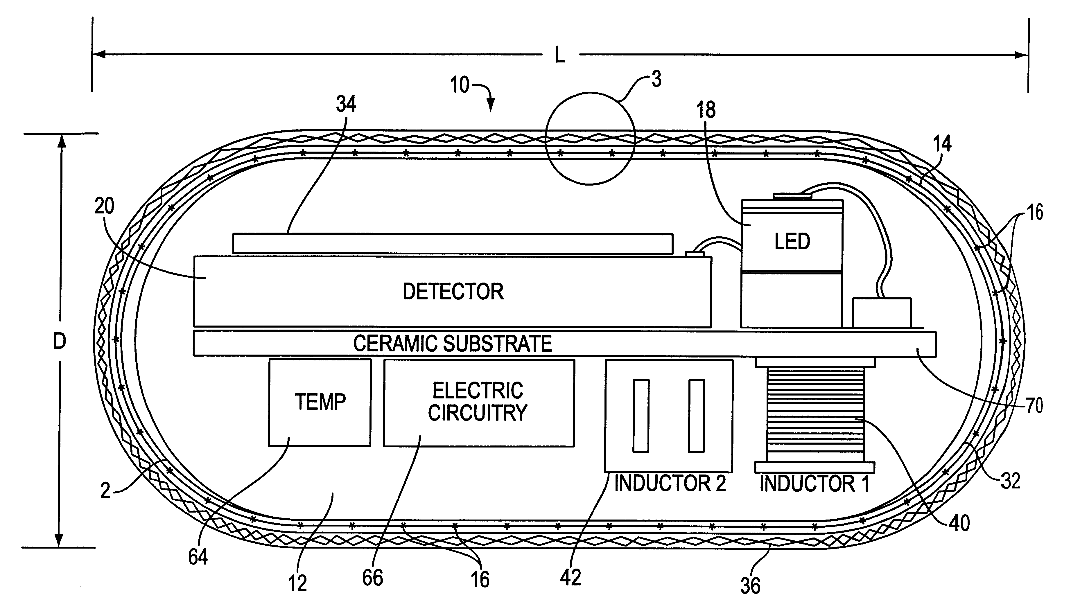
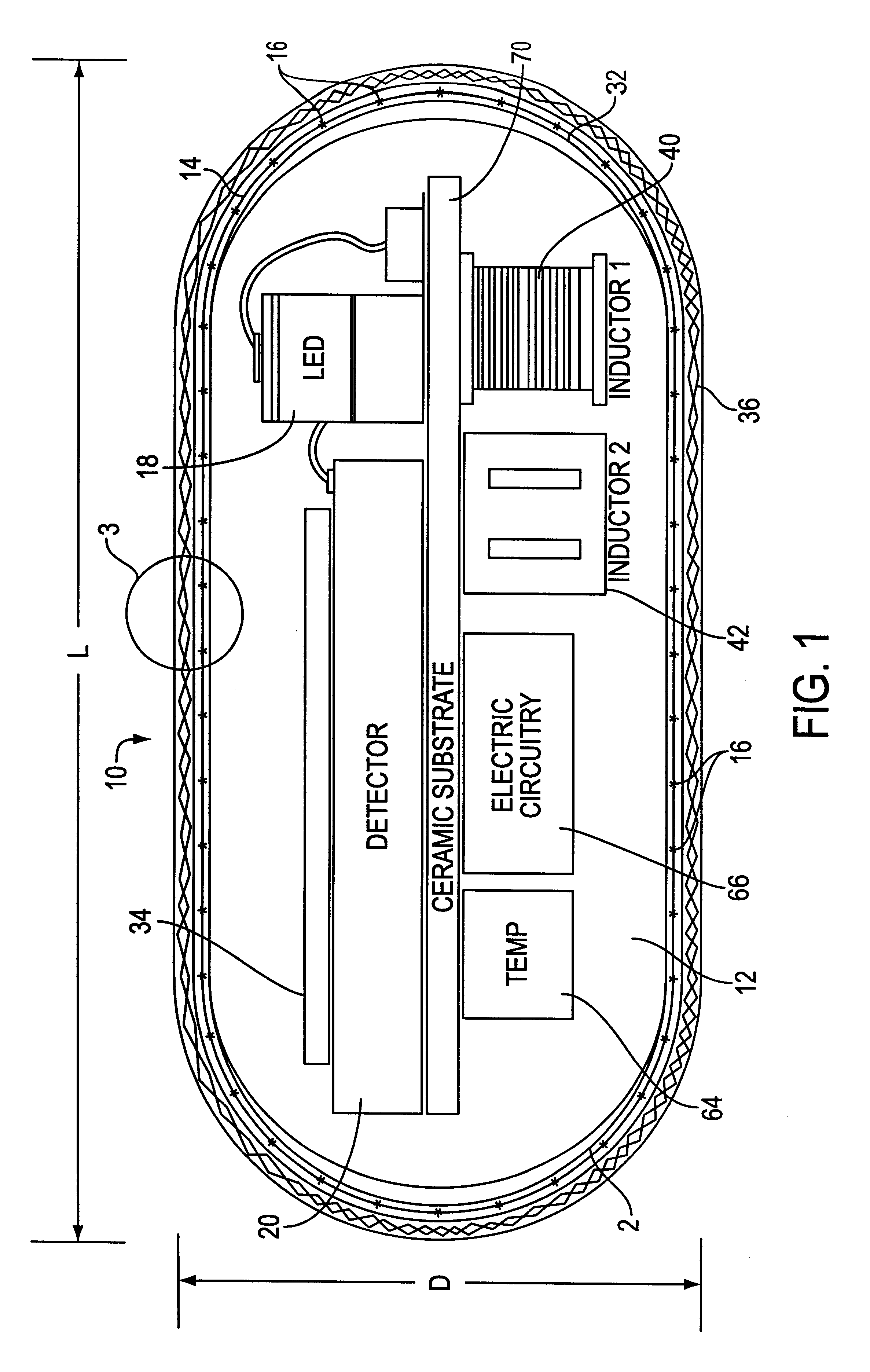
FIGS. 14(A)-14(B) illustrate a sensor 10 incorporating an optical reference channel. As shown, the sensor 10 preferably includes: a sensor body 12; an indicator membrane 14' having fluorescent indicator molecules distributed throughout the membrane; a reference membrane 14" having fluorescent control indicator molecules distributed throughout the membrane; a radiation source 18, such as for example a single LED similar to that described herein-above; an indicator channel photosensitive element 20-1, made, for example, similar to photosensitive element 20 described herein-above; a similar reference channel photosensitive element 20-2; a circuit substrate 70 (shown schematically with exemplary circuit elements 70i mounted thereto); a power source 40, such as for example an inductive power coil as shown; and a transmitter 42 such as for example a transmitter coil as shown. In any of the embodiments described herein, the membranes 14' and 14" can be made, for example, with materials sim...

second embodiment

Once again, the arrangement of the parts within the sensor can also be varied by those in the art. For example, FIGS. 17(C)-17(D) show a second embodiment similar to the embodiment shown in FIGS. 17(A)-17(B) with the indicator membrane 14' and the reference membrane 14" on the same side of the circuit board 70 and with a single radiation source, e.g., LED, 18--similar to the embodiments shown in FIGS. 14(A)-14(C). All of the applicable variations described above with respect to FIGS. 14(A)-14(C) and to FIGS. 17(A)-17(B) could be applied to the embodiment shown in FIGS. 17(C)-17(D).

As another example, FIGS. 17(E)-17(F) show another embodiment similar to the embodiment shown in FIGS. 17(A)-17(C) with the indicator membrane 14' and the reference membrane 14" on the same side of the circuit board 70 but with two radiation sources, e.g., LEDs, 18-1 and 18-2 similar to the embodiments shown in FIGS. 15(A)-15(C) but with the LEDs spaced further apart in the illustrated example. All of the ...


PUM


Abstract

An optical-based sensor for detecting the presence or amount of an analyte using both indicator and reference channels. The sensor has a sensor body with a source of radiation embedded therein. Radiation emitted by the source interacts with indicator membrane indicator molecules proximate the surface of the body. At least one optical characteristic of these indicator molecules varies with analyte concentration. For example, the level of fluorescence of fluorescent indicator molecules or the amount of light absorbed by light-absorbing indicator molecules can vary as a function of analyte concentration. In addition, radiation emitted by the source also interacts with reference membrane indicator molecules proximate the surface of the body. Radiation (e.g., light) emitted or reflected by these indicator molecules enters and is internally reflected in the sensor body. Photosensitive elements within the sensor body generate both indicator channel and reference channel signals to provide an accurate indication of the concentration of the analyte. Preferred embodiments are totally self-contained and are sized and shaped for use in vivo in a human being. Such embodiments preferably include a power source, e.g. an inductor, which powers the source of radiation using external means, as well as a transmitter, e.g. an inductor, to transmit to external pickup means the signal representing the level of analyte.

Description

1. Field of the InventionThe invention relates to electro-optical sensing devices for detecting the presence or concentration of an analyte in a liquid or gaseous medium. More particularly, the invention relates to (but is not in all cases necessarily limited to) optical-based sensing devices which are characterized by being totally self-contained, with a smooth and rounded oblong, oval, or elliptical shape (e.g., a bean- or pharmaceutical capsule-shape) and an extraordinarily compact size which permit the device to be implanted in humans for in-situ detection of various analytes.2. Background ArtU.S. Pat. No. 5,517,313, the disclosure of which is incorporated herein by reference, describes a fluorescence-based sensing device comprising indicator molecules and a photosensitive element, e.g., a photodetector. Broadly speaking, in the context of the field of the present invention, indicator molecules are molecules one or more optical characteristics of which is or are affected by the ...

Claims


Application Information

Patent Timeline
IPC IPC(8): A61B5/00G01N33/543G01N21/77G01N21/64G01N21/55G01N21/27
CPCA61B5/0031A61B5/076A61B5/14532A61B5/1459A61B5/6861G01N21/552G01N21/6428G01N21/648G01N21/77G01N21/7703G01N33/54373A61B5/14552A61B2560/0219A61B2562/12G01N2021/7773G01N2021/7783G01N2021/7786Y10S128/903
Inventor COLVIN, JR., ARTHUR E.DALE, GREGORY A.ZERWEKH, PAUL SAMUELLESHO, JEFFERY C.LYNN, ROBERT W.
Owner SENSEONICS INC
Why Eureka
Try Eureka