Check patentability & draft patents in minutes with Patsnap Eureka AI!

Apparatus for differential interpolation pulse width modulation digital-to-analog conversion and output signal coding method thereof

a technology of differential interpolation and pulse width, applied in the direction of transducer acoustic reaction prevention, transducer details, electrical transducers, etc., can solve the problems of short pulse width, less output signal gain, and stability problems of sigma-delta modulation, so as to increase the time domain resolution of pulse width

Active Publication Date: 2014-04-24
TRITAN TECH INC
View PDF9 Cites 1 Cited by
  • Summary
  • Abstract
  • Description
  • Claims
  • Application Information

AI Technical Summary

Benefits of technology

The present invention provides a digital to analog converter that uses differential interpolation pulse width modulation (iPWM) to achieve high fidelity audio output. The iPWM includes an input device for receiving digital audio data, a power driver for providing energy to a terminal load, and a filter for removing unwanted harmonic signals. The iPWM also has a PWM pulse generator for converting the digital input numerical code to a series of time domain pulse width, an interpolation unit for increasing the time domain resolution of the pulse width, a self-calibration unit for maintaining the pulse-width accuracy of the interpolation unit, and a differential pulse width generator for converting the series of PWM pulse into voltage and time domain differential form. The technical effect of this invention is to provide a more accurate and faithful conversion of digital audio data to analog audio signals for improved quality and performance.

Problems solved by technology

The drawback of the above embodiment is that sigma-delta modulation suffers stability problem and the modulator output signal gain is less than 1.
This is very short pulse-width for differential PWM implementation and may raise two issues.
The first issue is how to generate this short pulse while lowering the power consumption and cost; and the second issue is that the next stage of differential PWM output is a power driver stage, which will cause the short pulse diminished when signal pass through the power driver due to the dead-time and power MOS's parasitic capacitor, as shown in FIG. 10.

Method used


Image

  • Apparatus for differential interpolation pulse width modulation digital-to-analog conversion and output signal coding method thereof
  • Apparatus for differential interpolation pulse width modulation digital-to-analog conversion and output signal coding method thereof
  • Apparatus for differential interpolation pulse width modulation digital-to-analog conversion and output signal coding method thereof

Examples


Embodiment Construction

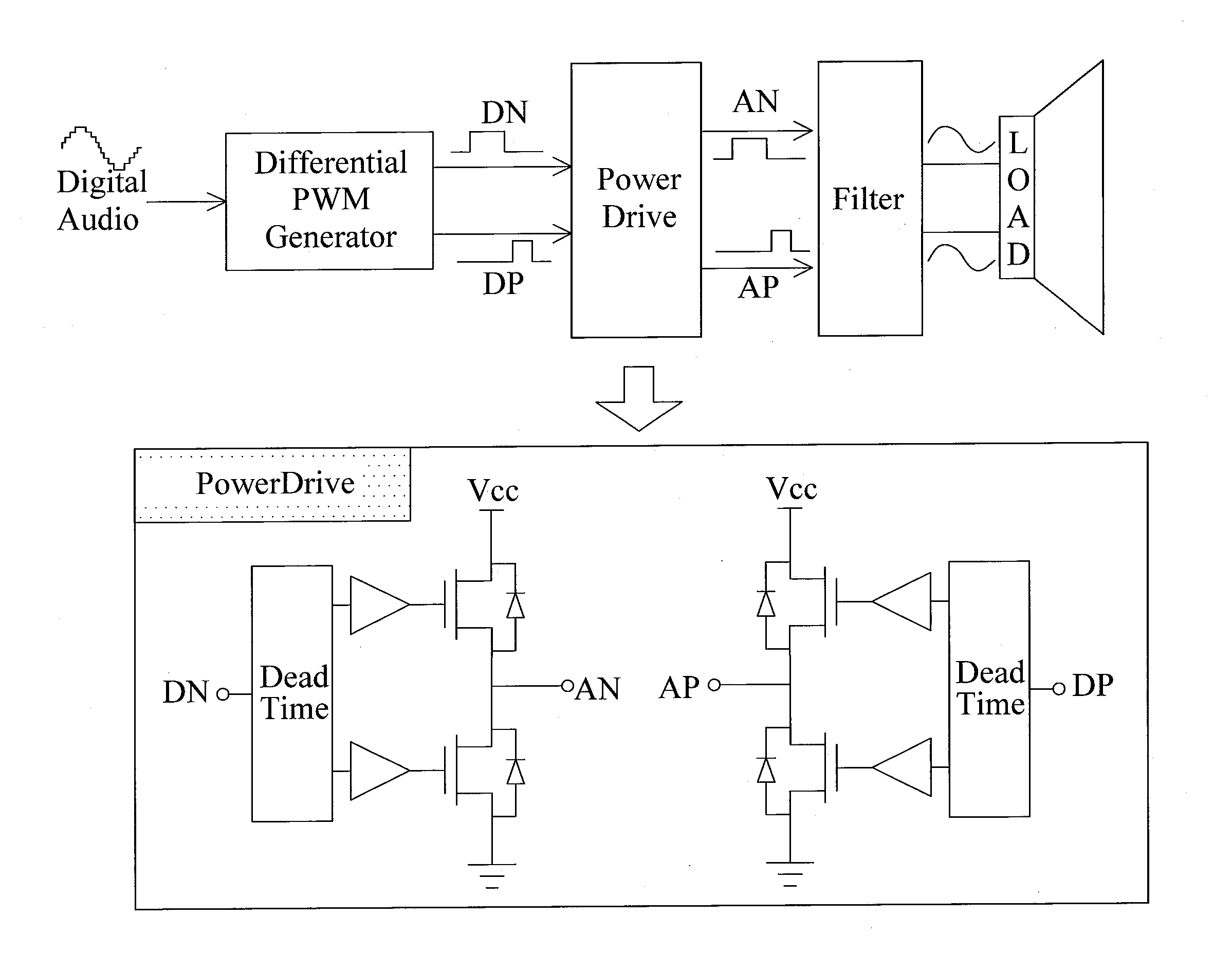
[0039]FIG. 11 shows a schematic view of a differential interpolation pulse width modulation (iPWM) DAC according to the invention. As shown in FIG. 11, the iPWM DAC includes an iPWM module 1110, a power drive stage 1120 and a filter 1130, wherein iPWM module 1110 is connected to a digital audio input and filter 1130 is connected to a terminal load 1140, for example, a speaker. iPWM module 1110 generates differential pulse according to the data stream from the digital audio input, power driver stage 1120 provides power to terminal load 1140 and filter 1130 removes unwanted harmonic signal to reconstruct analog signal outputted to terminal load 1140. iPWM module further includes a PWM 1111, an interpolation resolution unit 1112, a self-calibration unit 1113 and a differential pulse width generator 1114, wherein PWM 1111 converts the digital audio input to a series of time domain pulses with width; interpolation resolution unit 1112 increases time domain resolution of the pulse; self-c...


PUM


Abstract

A differential interpolation pulse width modulation (iPWM) digital to analog converter is provided, including an iPWM for generating differential pulse from an input digital audio data stream, a power driver for providing energy to a terminal load and a filter for removing unwanted harmonic signal to reconstruct analog signal, wherein the iPWM further includes a PWM pulse generator to convert the digital input numerical code to a series of time domain pulse width; an interpolation unit to increase the time domain resolution of the pulse width; a self-calibration unit to maintain the pulse-width accuracy of the interpolation unit; a differential pulse width generator to convert series of PWM pulse into voltage and time domain differential form.

Description

FIELD OF THE INVENTION[0001]The present invention generally relates to an apparatus for differential interpolation pulse width modulation (iPWM) digital-to-analog (DAC) conversion and output signal coding method thereof, and more specifically to an iPWM-DAC apparatus to generate high SNR PWM signal and forming voltage and time domain differential signal coding for iPWM-DAC output.BACKGROUND OF THE INVENTION[0002]A Class-D audio amplifier is a switching amplifier or PWM amplifier. Class-D amplifier usually can provide high power efficiency over 90%, comparison to the 50% provided by conventional linear amplifier. To obtain a high-SNR Class-D amplifier, a feedback loop is often included. FIG. 1 shows a schematic view of a conventional Class-D amplifier. As shown in FIG. 1, Class-D amplifier is embodied by a PWM generator 102 and a noise shaping sigma-delta modulator 101, wherein the PWM generator 102 outputs complementary signals to a power driver 103 and through a filter 104 to drive...

Claims


Application Information

Patent Timeline
Patent Type & Authority Applications(United States)
IPC IPC(8): H04R3/02
CPCH04R3/00
Inventor TSENG, CHING-HUNGPENG, SHEN-YU
Owner TRITAN TECH INC
Features
  • R&D
  • Intellectual Property
  • Life Sciences
  • Materials
  • Tech Scout
  • Unparalleled Data Quality
  • Higher Quality Content
  • 60% Fewer Hallucinations
Learn More