Systems and methods for intelligent monitoring of thoroughfares using thermal imaging

a technology of thermal imaging and thoroughfares, applied in the field of thermal imaging devices, can solve the problems of limited current traffic monitoring systems, affecting the detection accuracy of monitoring systems using such sensors, and affecting the influence of various environmental factors

Inactive Publication Date: 2014-04-24
FLIR SYST INC
View PDF7 Cites 103 Cited by
  • Summary
  • Abstract
  • Description
  • Claims
  • Application Information

AI Technical Summary

Benefits of technology

[0010]In one embodiment, an intelligent monitoring system includes an infrared imaging module disposed at a location along a thoroughfare, the infrared imaging module comprising a focal plane array (FPA) configured to capture thermal images of a scene comprising at least a portion of the thoroughfare; and a processor in communication with the infrared imaging module, the processor configured to analyze the thermal images to determine a presence of one or more objects and at least one attribute associated with the objects in the scene, and generate monitoring information based on the determination of the presence and the attribute.
[0011]In another embodiment, an intelligent monitoring method includes capturing, at a focal plane array (FPA) of an infrared imaging module, thermal images of a scene comprising at least a portion of a thoroughfare, wherein the infrared

Problems solved by technology

There have been some proposals for, and some limited implementations of, traffic monitoring systems used for active traffic management (e.g., variable speed limits, ramp metering, and traffic light control).
As such, current traffic monitoring systems are typically limited to providing some general description relating to vehicular traffic flow and/or density (e.g., estimated traffic flow rate) on highways, arterial roads, a

Method used


Image

  • Systems and methods for intelligent monitoring of thoroughfares using thermal imaging
  • Systems and methods for intelligent monitoring of thoroughfares using thermal imaging
  • Systems and methods for intelligent monitoring of thoroughfares using thermal imaging

Examples


Embodiment Construction

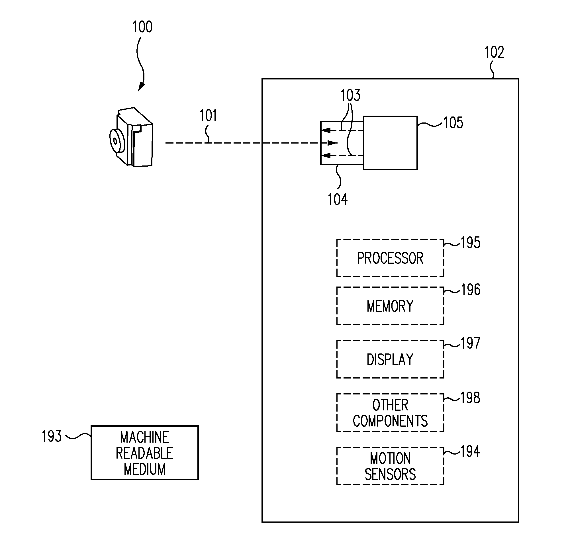
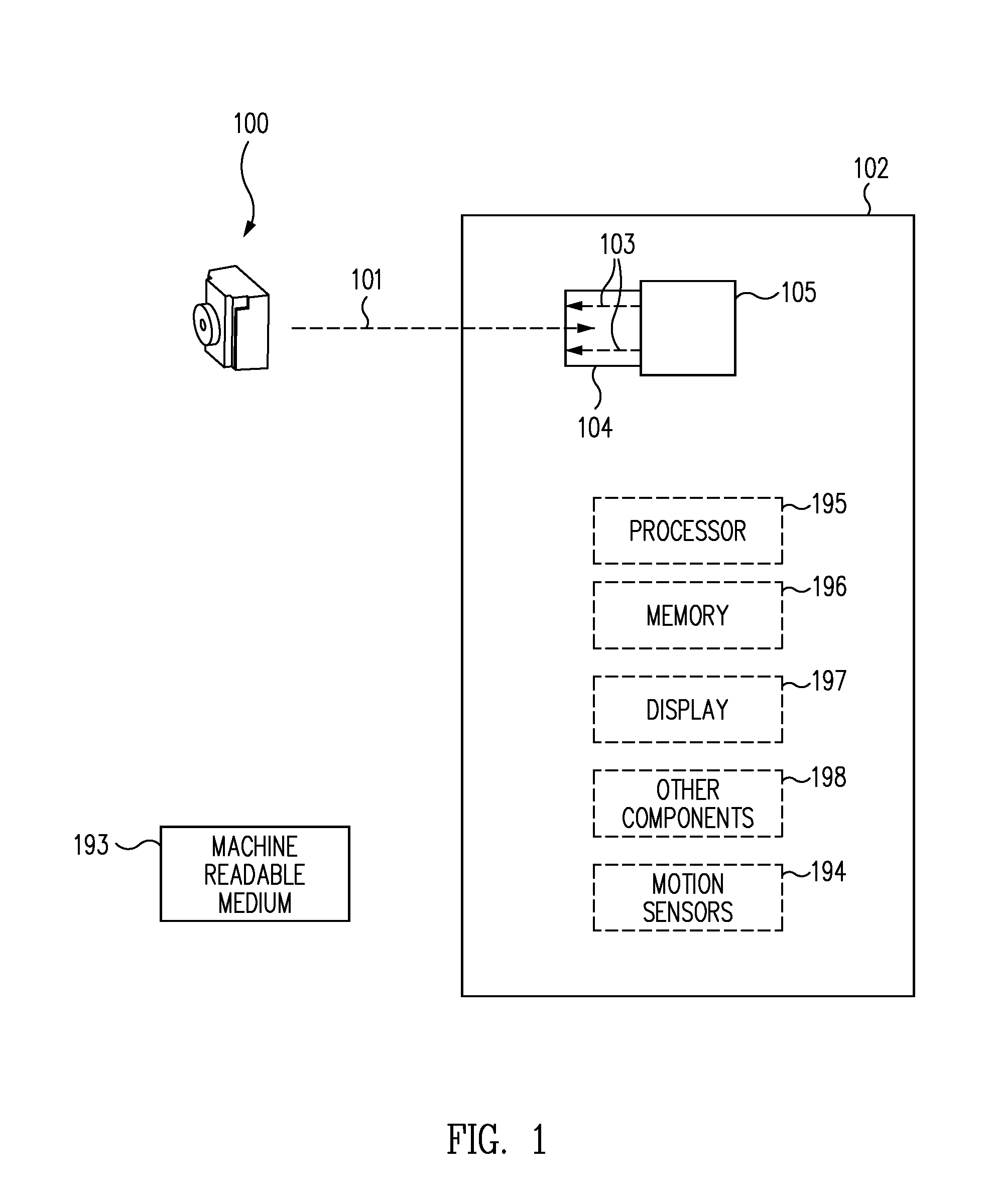
[0030]FIG. 1 illustrates an infrared imaging module 100 (e.g., an infrared camera or an infrared imaging device) configured to be implemented in a host device 102 in accordance with an embodiment of the disclosure. Infrared imaging module 100 may be implemented, for one or more embodiments, with a small form factor and in accordance with wafer level packaging techniques or other packaging techniques.

[0031]In one embodiment, infrared imaging module 100 may be configured to be implemented in a small portable host device 102, such as a mobile telephone, a tablet computing device, a laptop computing device, a personal digital assistant, a visible light camera, a music player, or any other appropriate mobile device. In this regard, infrared imaging module 100 may be used to provide infrared imaging features to host device 102. For example, infrared imaging module 100 may be configured to capture, process, and / or otherwise manage infrared images and provide such infrared images to host de...


PUM


Abstract

Various techniques are disclosed for systems and methods using thermal imaging to intelligently monitor thoroughfares. For example, an intelligent monitoring system may include an infrared imaging module, a processor, a communication module, a memory, and an adjustable component. The system may be mounted, installed, or otherwise disposed at various locations along thoroughfares, and capture thermal images of a scene that includes at least a portion of the thoroughfares. Various thermal image processing and analysis operations may be performed on the thermal images to generate comprehensive monitoring information including an indication of detected objects in the scene and at least one attribute associated with the objects. Various actions may be taken, such as generating various alarms and intelligently adjusting operation of various adjustable devices on thoroughfares, based on the monitoring information. The monitoring information may be shared among multiple instances of the system, and may be communicated to external devices.

Description

CROSS-REFERENCE TO RELATED APPLICATIONS[0001]This application is a continuation of International Patent Application No. PCT / US2012 / 41755 filed Jun. 8, 2012 which claims priority to U.S. Provisional Patent Application No. 61 / 656,841 filed Jun. 7, 2012 and entitled “SYSTEMS AND METHODS FOR INTELLIGENT MONITORING OF THOROUGHFARES USING THERMAL IMAGING” which are both hereby incorporated by reference in their entirety.[0002]International Patent Application No. PCT / US2012 / 41755 claims the benefit of U.S. Provisional Patent Application No. 61 / 545,056 filed Oct. 7, 2011 and entitled “NON-UNIFORMITY CORRECTION TECHNIQUES FOR INFRARED IMAGING DEVICES” which is hereby incorporated by reference in its entirety.[0003]International Patent Application No. PCT / US2012 / 41755 claims the benefit of U.S. Provisional Patent Application No. 61 / 495,873 filed Jun. 10, 2011 and entitled “INFRARED CAMERA PACKAGING SYSTEMS AND METHODS” which is hereby incorporated by reference in its entirety.[0004]Internatio...

Claims


Application Information

Patent Timeline
IPC IPC(8): G01V8/10H05B37/02G01N21/17G06V10/143
CPCG01V8/10H05B37/0209H05B37/02G01N21/17H04N5/33Y02B20/40H05B47/115G06V20/54G06V10/143
Inventor FRANK, JEFFREY D.HOGASTEN, NICHOLASHOELTER, THEODORE R.STRANDEMAR, KATRIN
Owner FLIR SYST INC
Why Eureka
Try Eureka