Self-lighting device for a cigarette

Inactive Publication Date: 2014-04-24
ETIENNE LACROIX TOUS ARTIFICES
View PDF2 Cites 2 Cited by
  • Summary
  • Abstract
  • Description
  • Claims
  • Application Information

AI Technical Summary

Problems solved by technology

And the more the strip is worn, the more difficult it is to light a cigarette.
In practice, the secondary chemical material is:either conditioned on one of the faces of the cigarette pack in such a way that during the manipulation of said pack, said secondary chemical mate

Method used


Image

  • Self-lighting device for a cigarette
  • Self-lighting device for a cigarette
  • Self-lighting device for a cigarette

Examples


Embodiment Construction

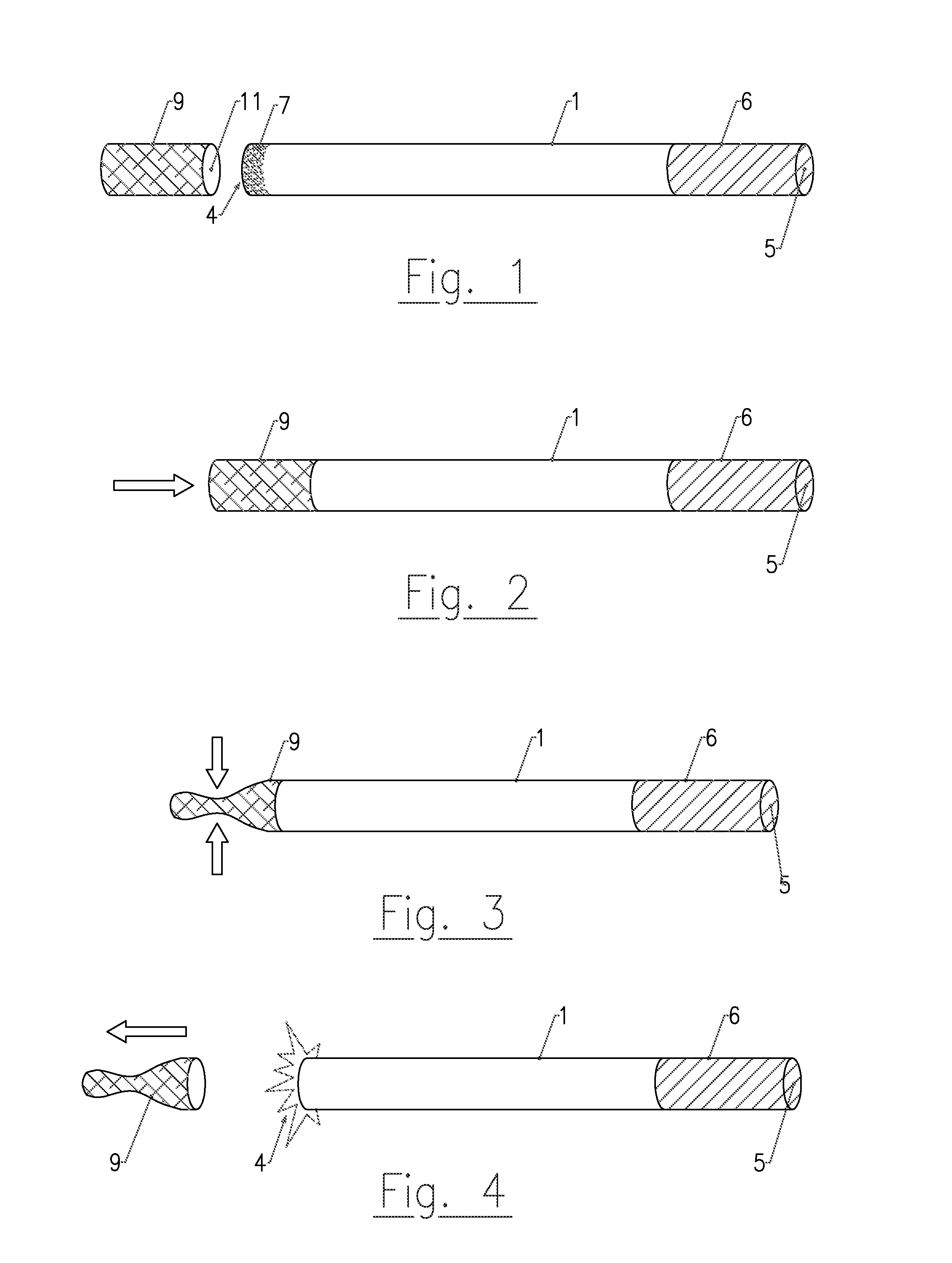
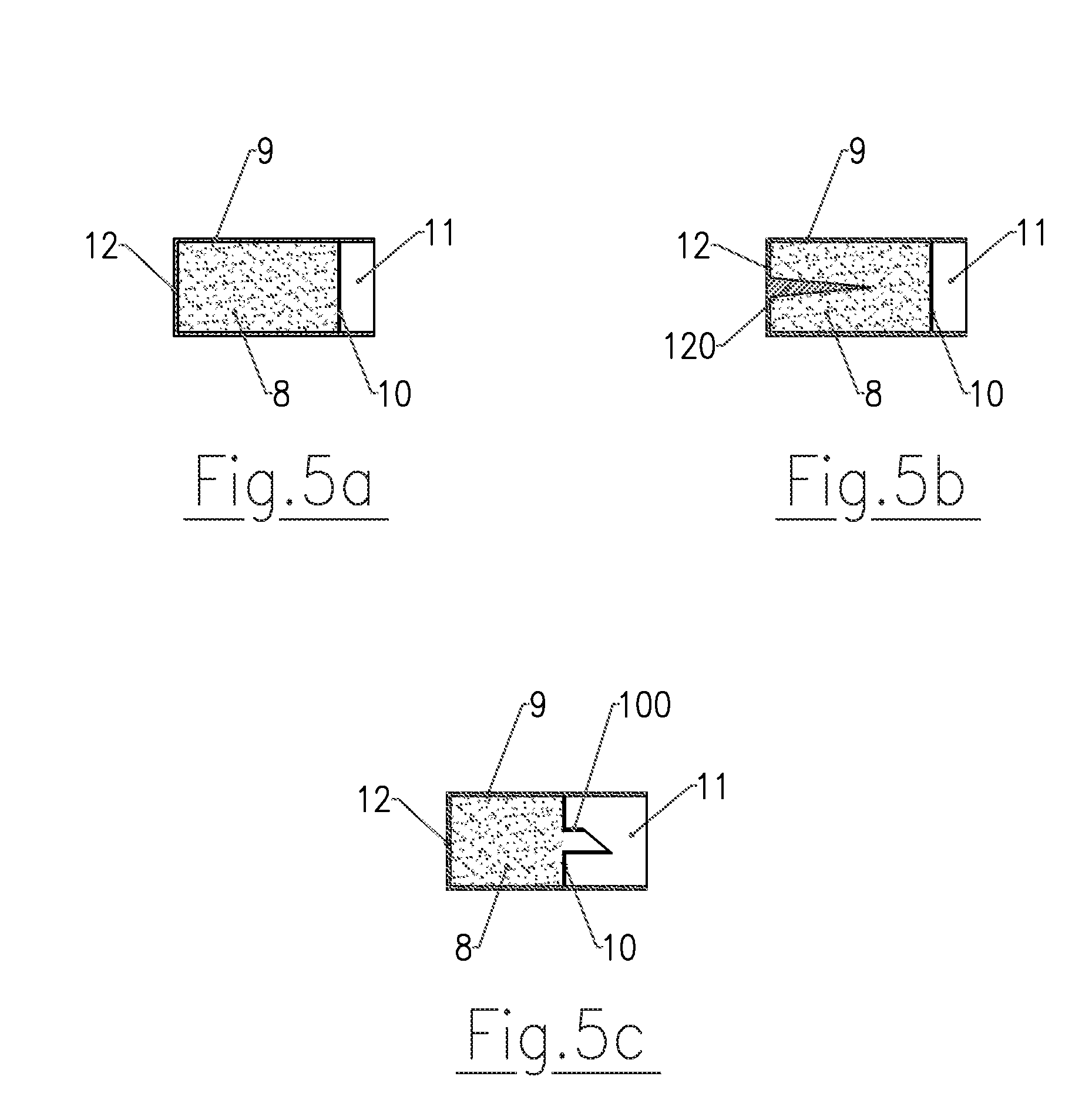
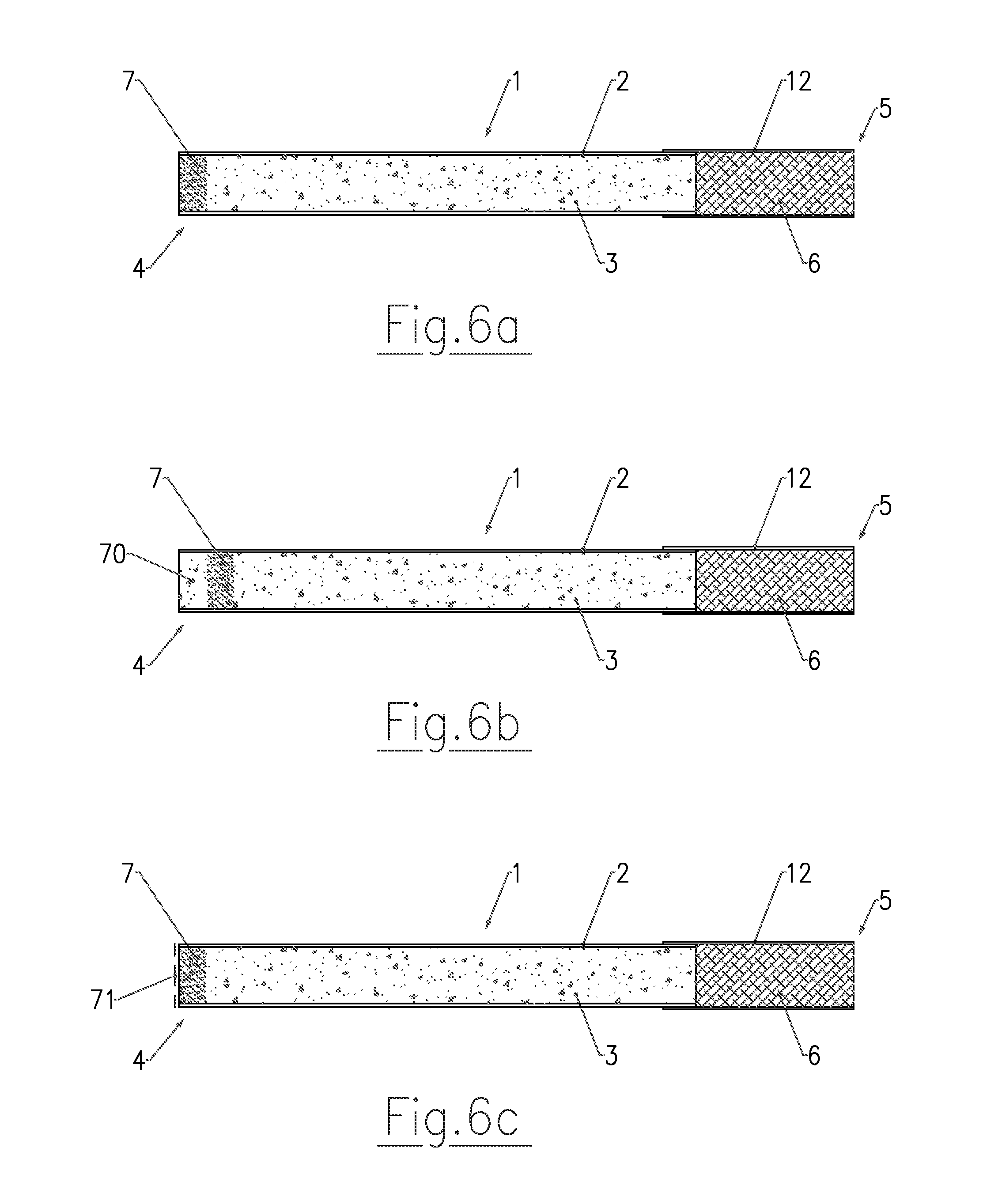
[0034]The invention makes it possible to self-light a cigarette 1. “Cigarette” means a conventional cigarette with or without a filter, a cigarillo, a cigar, or other similar object that can be consumed by a smoker. As shown diagrammatically in FIGS. 1 to 4, a cigarette 1 generally has the shape of a cylinder formed from a sheet of paper 2 and inside of which are arranged chopped leaves of tobacco 3. It has a diameter that can vary from 3 mm to 7 mm and a length that can vary from 60 mm to 100 mm. It comprises a end to be lit 4 and an inhalation end 5 opposite said end to be lit. The inhalation end 5 can in particular comprise a filter 6.

[0035]The self-lighting device of the invention comprises a primary chemical material 7 (or material “to be lit”) intended to be placed at the end to be lit 4 of the cigarette 1. The primary chemical material 7 can be put into place via impregnation, coating, compression, insertion into the leaves of tobacco 3, of a liquid, gel, solid, powder, micro...


PUM


Abstract

The invention relates to a self-lighting device for a cigarette, comprising a primary chemical material (7) to be placed at the lighting end (4) of the cigarette (1); and a secondary chemical material (8) that is incompatible with the primary material (7), said primary and secondary materials being inflammable when they come into contact with each other. The device is characterised in that the secondary material (8) is arranged in a receptacle (9) designed to fit over the lighting end (4) of the cigarette (1), bringing the secondary material into contact with the primary material (7).

Description

TECHNICAL FIELD OF THE INVENTION[0001]The invention relates to a self-lighting device for a cigarette.[0002]It relates to the technical field of pyrotechnical devices and more particularly those intended for lighting cigarettes and supplying an alternative to the conventional means of the lighter or match type.PRIOR ART[0003]Devices for self-lighting cigarettes illustrating prior art are described in the following patent documents: FR 2 905 231 (Charli ABISDID), BG 407 714 (M. MARGOLIS), DE 3 509 293 (LIECHTENSTEIN RICHARD VON), EP 0 066 021 (Y00, BYUNG EON) FR 7 539 535 (TOKYO ENGINEERING CO.) D5: GB 314 145 (Piedad and Alejandro LIFCHUZ), FR 709 175 (Giulio TURRI), JP 2005 5 224 232 (ISHIKAWA JOJI), GB 406 153 (Ansley HERMAN FOX). These devices comprise an ignition material configured to ignite a flammable material under the effect of an impact or friction. The friction strips generally used, are worn as the cigarettes are lit. And the more the strip is worn, the more difficult it...

Claims


Application Information

Patent Timeline
IPC IPC(8): C06C9/00F23Q2/02F24J1/00F24V30/00
CPCC06C9/00F24J1/00F23Q2/02A24D1/08F24V30/00
Inventor ABISDID, MARLENEABISDID, CHARLIMEDUS, DOMINIQUETHEBAULT, PIERRE
Owner ETIENNE LACROIX TOUS ARTIFICES
Why Eureka
Try Eureka