Quick Release Roller Sleeve Mounting Hub

a technology of roller sleeves and hubs, which is applied in the direction of bearings, portable power tools, printing, etc., can solve the problems of increasing production time, increasing production costs, and several wasted batches of products,

Active Publication Date: 2014-04-24
FRC HLDG
View PDF14 Cites 9 Cited by
  • Summary
  • Abstract
  • Description
  • Claims
  • Application Information

AI Technical Summary

Benefits of technology

[0008]The present apparatus may be described as a quick release roller sleeve and mounting hub for mounting to a high speed machine for printing, metal flattening or other similar functions. The quick release roller sleeve is configured to mount over and around the mounting hub or core of the assembly. Each roller sleeve is constructed of fiberglass or other composite type material with an elastomeric covering. The roller sleeve fits around the mounting hub and is sandwiched between an inward facing flange and an outward facing flange, both of which completely circumscribe the hub. Each of the flanges has a circumferential notch that mounts against the sleeve base capturing and containing the sleeve between the flanges with the sleeve supported by the hub or core. The flange notches allow for the sleeves to be appropriately positioned within the flanges and around the hub or core so that the roller sleeve, when worn and needing to be replaced, is able to slide into and out of place for ease of mounting and dismounting. The present invention allows for the existing core to remain in its aligned position on the machinery while changing only the roller sleeve portion, which allows for the entire assembly to maintain its original configuration.

Problems solved by technology

The manner in which roller sleeves are currently being mounted and demounted on the roll cores has caused problems in terms of increasing time of production due to the time required in changing the sleeve and core together which can take up to an hour or more during which time the machine onto which the roller sleeve is being mounted is shut down.
Moreover, once a sleeve and core have been changed there may be issues with alignment which can lead to several wasted batches of product while the user makes alignment corrections which adds more downtime to production.

Method used


Image

  • Quick Release Roller Sleeve Mounting Hub
  • Quick Release Roller Sleeve Mounting Hub
  • Quick Release Roller Sleeve Mounting Hub

Examples


first embodiment

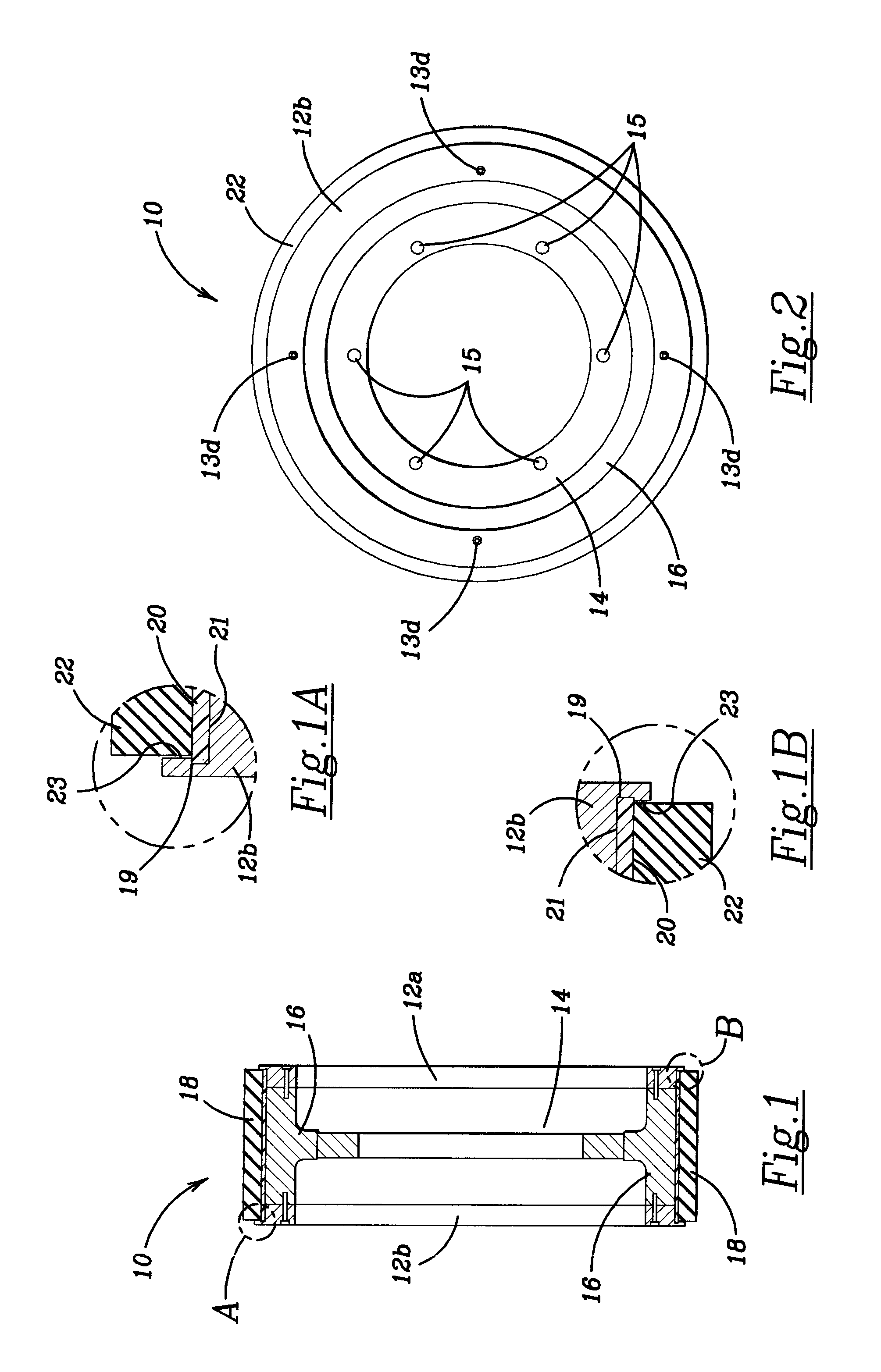
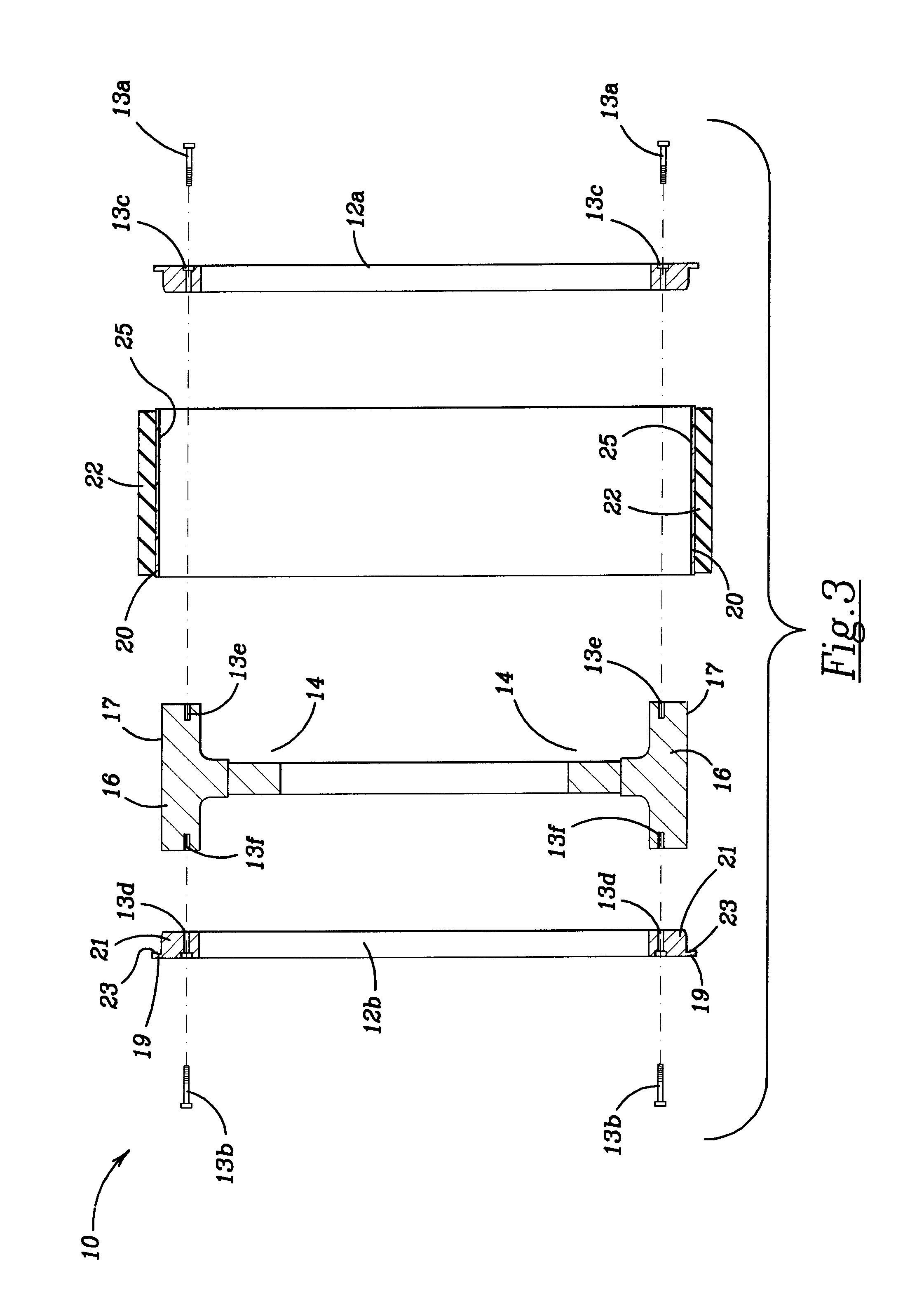
[0028]FIG. 2 shows an outer front face view of the quick release roller sleeve mounting hub assembly 10 of the present invention. In this first embodiment, the quick release assembly 10 has a large diameter mounting hub 14 including a set of six apertures 15 through which a series of fastening means extend for attaching the mounting hub 14 to the machinery. The apertures 15 are spaced about the inner circumferential opening of the mounting hub 14 at points approximating 60° separations between each of them. Shown in the inner flange plate 12b are a set of four mounting apertures 13d for mounting the flange plate to the mounting hub 14. As can be seen from FIG. 3, the outer flange plate 12a also has a set of four mounting apertures 13c for mounting the flange plate 12a to the mounting hub 14. The mounting apertures 13c, 13d are spaced about the periphery of the outer flange plates 12a, 12b at points approximating 90° separations between each of them.

[0029]Referring now to FIG. 3, the...

second embodiment

[0032]Shown in FIG. 4 is the quick release roller sleeve and mounting hub assembly 110 of the present invention having a differently sized central aperture for mounting to a roller hub. The quick release assembly is comprised of a pair of opposing inner and outer flange plates 112a, 112b, a mounting hub 114 having an outward facing support rim 116, and a roller sleeve 118. The inner flange plate 112a is secured to the support rim 116 across an inner space 130 dimensioned exactly to the length of quadrilaterally positioned spacer blocks 132a-132d mounted to the inner flange plate 112a. The spacer blocks 132b and 132d overlie one another in the view presented with spacer block 132b shown in phantom lines. The quadrilaterally positioned spacer blocks 132a-132d extend across the inner space 130 and provide a connecting point for the support rim 116 as well as a positioning and mounting point for the roller sleeve 118 that extends around the outer circumference of the outer flange plate ...

third embodiment

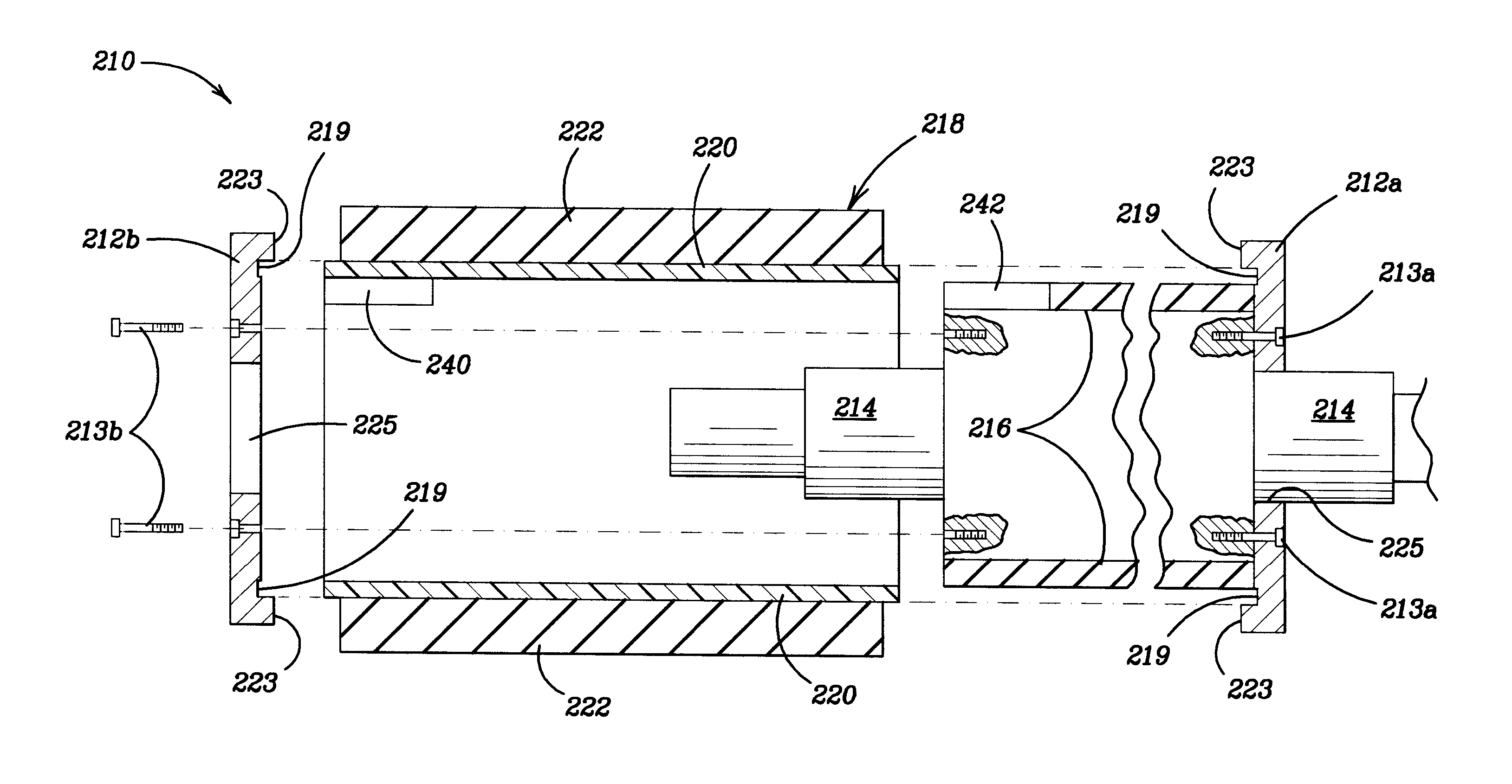
[0039]the quick release roller sleeve and mounting hub assembly 210 of the present invention is presented in FIGS. 7, 8. The quick release assembly is comprised of a pair of opposing inner and outer flange plates 212a, 212b, a mounting hub 214 having an outer support surface 216, and a roller sleeve 218. In this embodiment the exploded view of FIG. 8 depicts the outward facing side of the quick release assembly to the left instead of the right as was done in the prior two embodiments to demonstrate that the invention will work regardless of the mounting position. The inner flange plate 212a is secured to the support surface 216 across the inward face of the hub 214 by a set of mounting screws 213a. Likewise, the outer flange plate 212b is secured to the support rim 216 across the outward face of the hub 214 by a set of mounting screws 213b. The outer flange plate 212b captures the base 220 of roller sleeve 218 within cooperating notch 219 slightly inward of the outer edge of the fla...


PUM

PropertyMeasurementUnit
lengthaaaaaaaaaa
lengthaaaaaaaaaa
diameteraaaaaaaaaa

Abstract

A quick release roller sleeve and mounting hub assembly is described for use with high speed roller machines. The assembly includes an outer flange plate that can be detached from the assembly in order for the roller sleeve to be dismounted and a new roller sleeve mounted as the existing roller sleeve becomes worn and needs to be replaced. The quick release permits the mounting hub and other parts of the assembly to remain in their aligned configuration and positions while only exchanging the roller sleeve portion of the assembly.

Description

BACKGROUND OF THE INVENTION[0001]The invention generally resides in the field of quick release roller sleeves. Roller sleeves, which are mountable and demountable from rollers and other hub-like cylindrical structures, are used in several forms of printing, metal flattening, and other manufacturing processes.[0002]The manner in which roller sleeves are currently being mounted and demounted on the roll cores has caused problems in terms of increasing time of production due to the time required in changing the sleeve and core together which can take up to an hour or more during which time the machine onto which the roller sleeve is being mounted is shut down. Moreover, once a sleeve and core have been changed there may be issues with alignment which can lead to several wasted batches of product while the user makes alignment corrections which adds more downtime to production. Accordingly there exists a need for a quick release roller sleeve mounting hub, which cuts down significantly ...

Claims


Application Information

Patent Timeline
Patent Type & Authority Applications(United States)
IPC IPC(8): F16C13/00
CPCF16C13/00B41N7/00Y10T29/49558
Inventor SHERIDAN, JOSEPH M.
Owner FRC HLDG
Why Eureka
Try Eureka