Determining Trajectories of Redundant Actuators Jointly Tracking Reference Trajectory

Inactive Publication Date: 2014-04-24
MITSUBISHI ELECTRIC RES LAB INC
View PDF4 Cites 27 Cited by
  • Summary
  • Abstract
  • Description
  • Claims
  • Application Information

AI Technical Summary

Benefits of technology

[0023]In yet another embodiment of the invention, one particular quadratic, program is a parallel quadratic programming solver that converts a quadratic program into a dual form that transforms the constraints to be in a positive cone. Parallel implementations offer the advantage of fast computation times, and

Problems solved by technology

The operation of such redundant actuators is complicated by the fact that each point on the reference trajectory representing, e.g., a cutting path for a laser cutting machine, can be achieved by various, i.e., not unique, combinations of motions of the

Method used


Image

  • Determining Trajectories of Redundant Actuators Jointly Tracking Reference Trajectory
  • Determining Trajectories of Redundant Actuators Jointly Tracking Reference Trajectory
  • Determining Trajectories of Redundant Actuators Jointly Tracking Reference Trajectory

Examples


Example

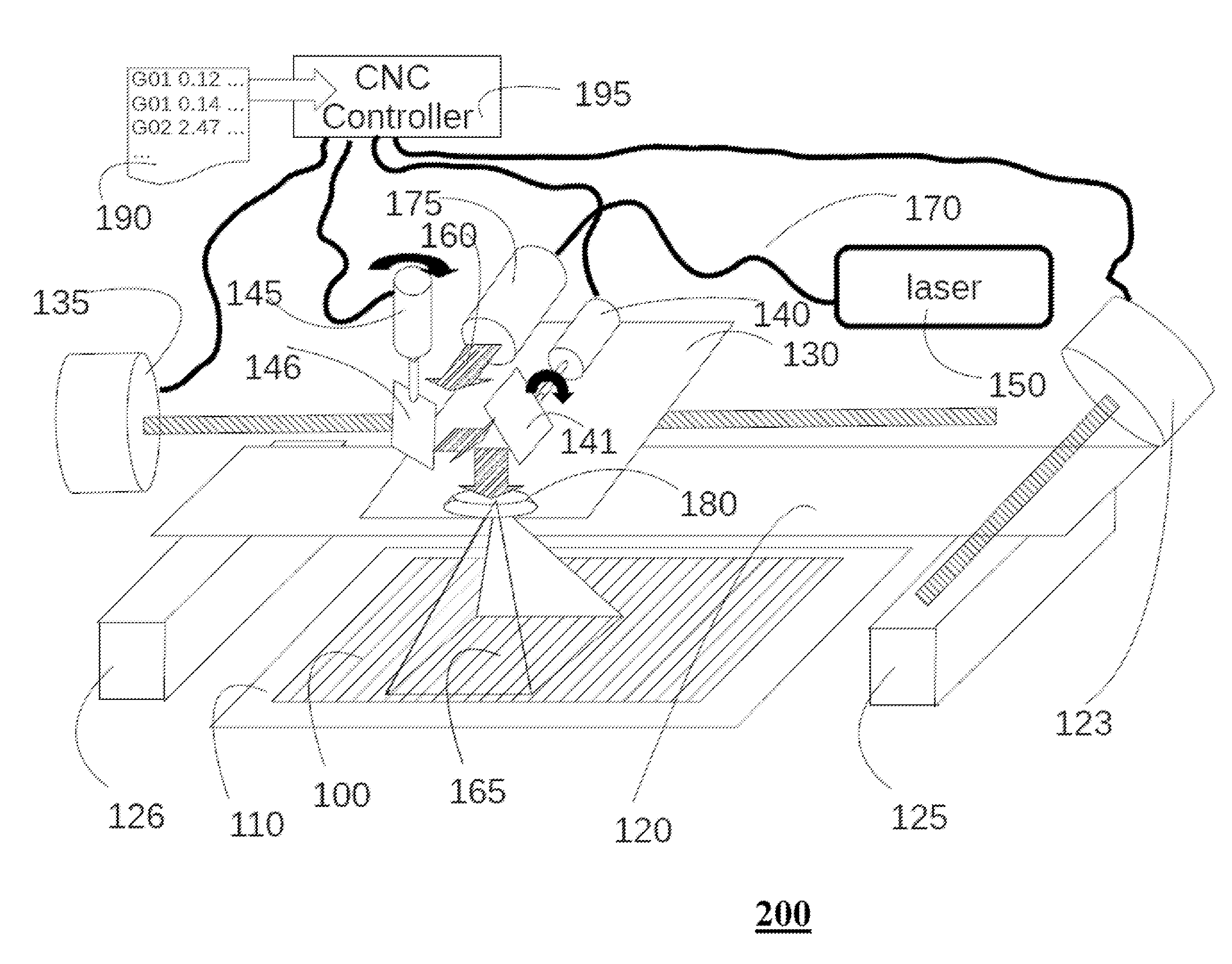
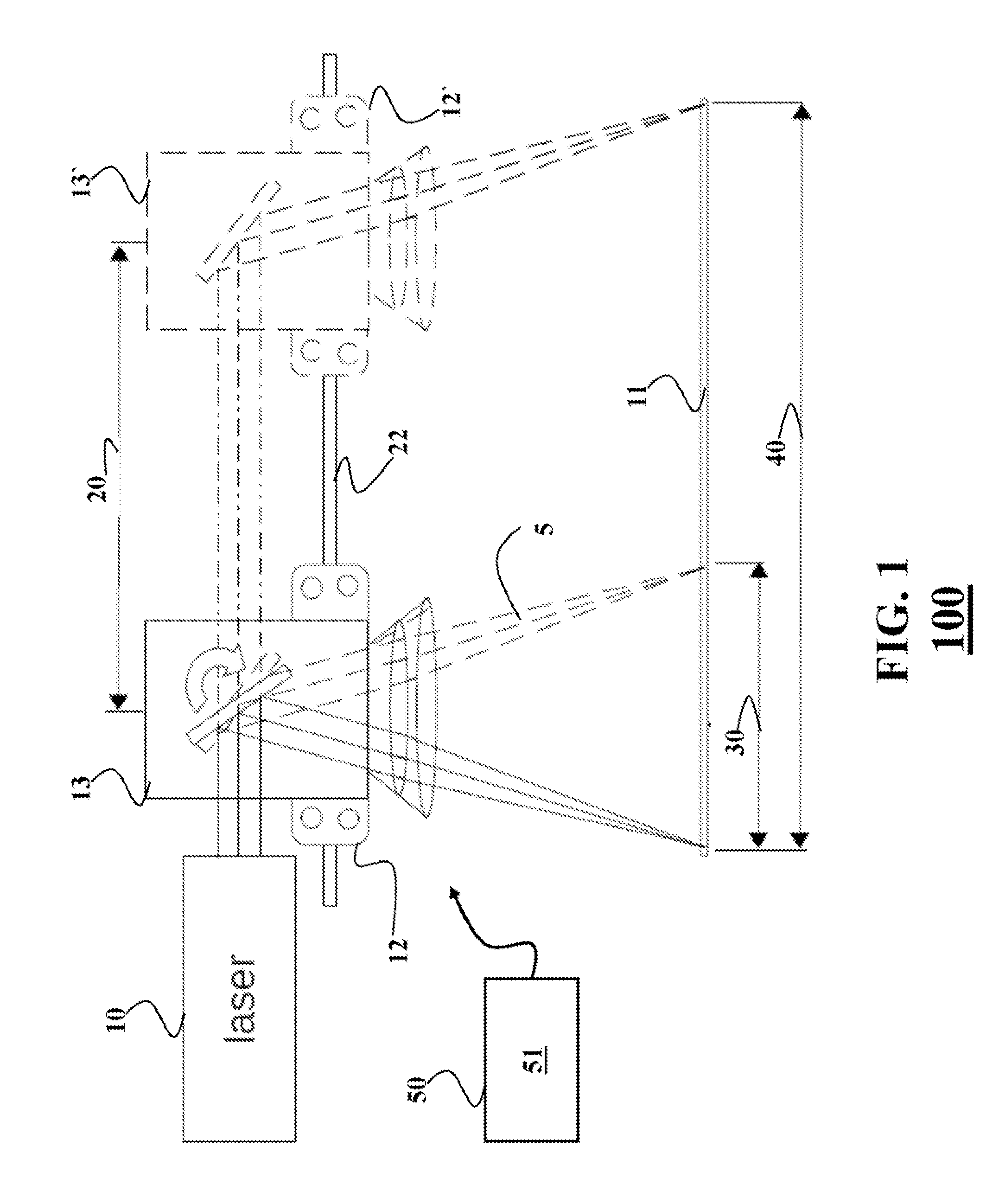
[0041]FIG. 1 shows a block diagram of an exemplar machine having redundant actuators. The redundant actuators operate substantially concurrently for at least one direction of motion or operation. An example is a laser cutting machine 100. The laser cutting machine 100 is suitable for controlling a position of a beam produced by a laser 10 with respect to a workpiece 11. The laser cutting machine 100 includes redundant actuators, i.e., a first actuator and a second actuator, such that a laser beam travels along a first direction 20. However, the principles of the invention can be employed by any type of redundant actuators.

[0042]The laser cutting machine includes a first actuator, e.g., a platform 12 configured to move along at least the first direction 20. The platform is moved by a motion system 22 for moving the platform in a plane parallel to the workpiece. In one embodiment, the motion system 22 includes a first prismatic joint facilitating a first motion of the platform along t...


PUM


Abstract

A method determines trajectories of redundant actuators of a machine including a first actuator and a second actuator. The method determines a first trajectory of the first actuator tracking a reference trajectory with an error tolerance, wherein the error tolerance is a function of a constraint of the second actuator, and determines a second trajectory of the second actuator based on a difference between the reference trajectory and the first trajectory.

Description

FIELD OF THE INVENTION[0001]This invention relates generally to controlling an operation of a machine having redundant actuators, and more particularly to determining trajectories of the redundant actuators jointly tracking a reference trajectory.BACKGROUND OF THE INVENTION[0002]Common methods for operating laser cutting machines perform two-dimensional (2D) relative motion between a laser beam and a workpiece, such that the laser beam cuts the workpiece as the beam moves. In such machines, there are three options. A position of the laser is fixed and the workpiece is moved in X and Y directions. A position of the workpiece is fixed and the laser or a mirror in the beam path is moved in the X and the Y directions. The laser is fixed in the Y direction and the beam in the X direction, and the workpiece is fixed in X direction and moves in Y direction.[0003]A limiting factor on the production rate of electromechanical machine, such as laser cutting machines, is directly related to the...

Claims


Application Information

Patent Timeline
IPC IPC(8): G05B13/02
CPCG05B19/19G05B2219/25472G05B2219/41194G05B2219/41195G05B2219/50218
Inventor SHILPIEKANDULA, VIJAYBRAND, MATTHEWSRIKANTH, MANOHARBORTOFF, SCOTT A.
Owner MITSUBISHI ELECTRIC RES LAB INC
Why Eureka
Try Eureka