Supercharge Your Innovation With Domain-Expert AI Agents!

Fixing member manufacturing method and fixing member manufacturing apparatus

a manufacturing method and fixing member technology, applied in the direction of electrographic process, electrographic process apparatus, instruments, etc., can solve the problems of high manufacturing cost, unsatisfactory squeezing step, and non-uniform rotation,

Active Publication Date: 2014-05-01
CANON KK
View PDF3 Cites 6 Cited by
  • Summary
  • Abstract
  • Description
  • Claims
  • Application Information

AI Technical Summary

Benefits of technology

The technical effect of this patent is to provide a way to make a fixing member that can properly remove excess adhesive between a resin tube and an elastic material.

Problems solved by technology

However, in such a tube coating method using the metal mold, if a center axis of the core metal and a center axis of the inner peripheral surface of the metal mold are not accurately coincide with each other, cylindricity after manufacturing is deviated, so that rotation non-uniformity is undesirably generated during use.
For that reason, in order to bring a degree of run-out of a fixing roller within a predetermined range, the center axis of the roller and the center axis of the metal mold inner peripheral surface are required to be coincide with each other with high accuracy, and thus the metal mold having high shape accuracy is needed, so that there was a problem of a high manufacturing cost.
However, in this method, in the case where the elastic material and the outer diameter of the resin tube have variations due to production error, the diameter of the squeezing R is a certain diameter, and therefore there is a fear that the squeezing step cannot be performed properly.
However, in this method, as described in Comparison example appearing hereinafter, the squeezing step is performed by the air while maintaining a non-contact state of the ring member with the resin tube, and therefore there is a fear that the squeezing of the adhesive cannot be properly made.

Method used


Image

  • Fixing member manufacturing method and fixing member manufacturing apparatus
  • Fixing member manufacturing method and fixing member manufacturing apparatus
  • Fixing member manufacturing method and fixing member manufacturing apparatus

Examples


embodiment 1

(1) Image Forming Apparatus

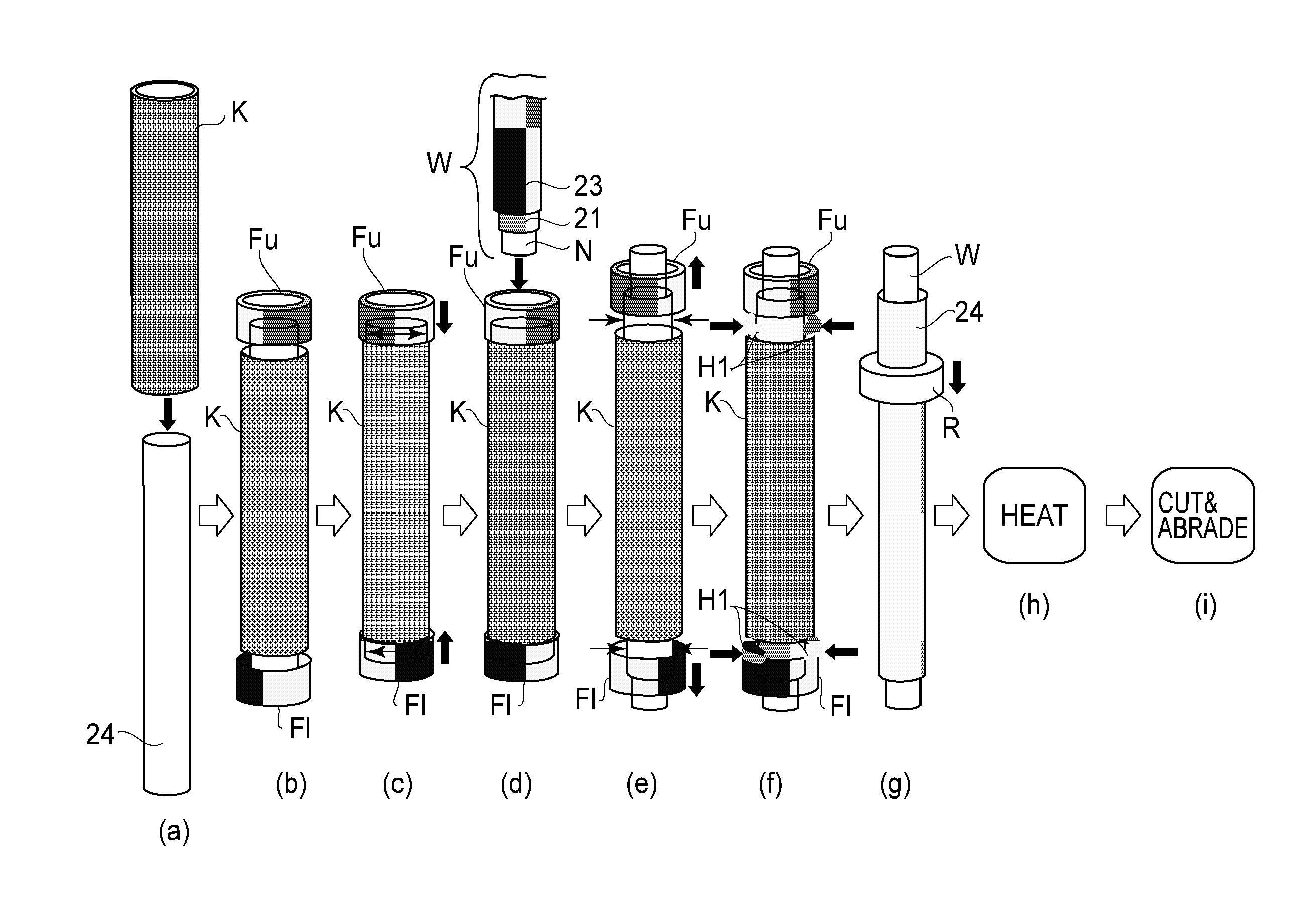
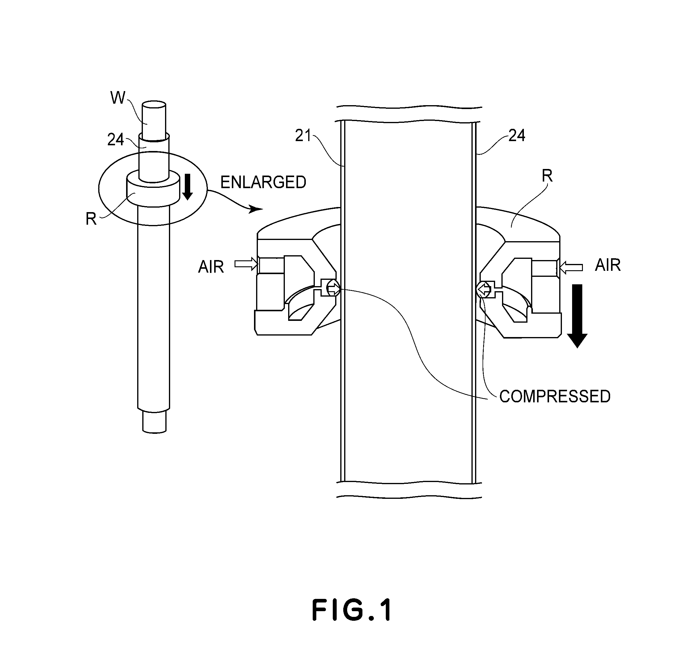
[0027]FIG. 3 is a schematic illustration showing a general structure of an image forming apparatus used in this embodiment. An image forming apparatus 1 is a laser printer of an electrophotographic type and includes a photosensitive drum 2 as an image bearing member for bearing a latent image. The photosensitive drum 2 is rotationally driven in the clockwise direction at a predetermined peripheral speed, so that an outer surface of the photosensitive drum 2 is electrically charged uniformly to a predetermined polarity and a predetermined potential. The uniformed charged surface of the photosensitive drum 2 is exposed to laser light 5 based on image information by a laser scanner (optical device) 4. As a result, on the surface of the photosensitive drum 2, an electrostatic latent image corresponding to the image information of the laser light is formed.

[0028]The electrostatic latent image is developed as a toner image by a developing device 6. The toner ima...

embodiment 2

[0133]Embodiment 2 will be described. Constituent elements (members) identical in constitution to those in Embodiment 1 are represented by the same reference numerals or symbols as those in Embodiment 1 and will be omitted from detailed description. In this embodiment, the fixing belt manufacturing method in Embodiment 1 is applied to a pressing belt manufacturing method.

(1) Pressing Belt 30

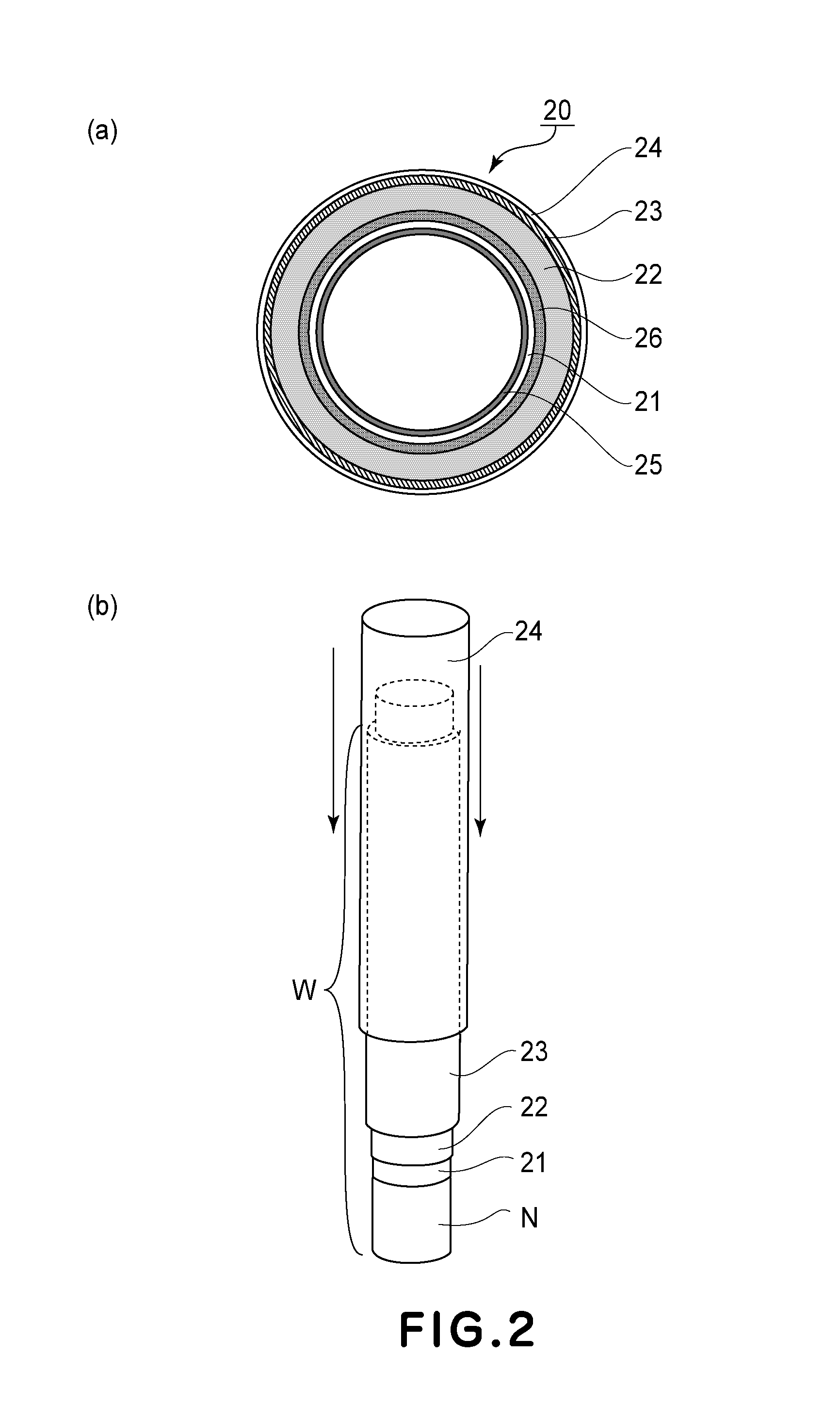
[0134]In this embodiment, with respect to also a layer structure of the pressing belt 30, as the other fixing member of the fixing device, the same layer structure as that of the fixing belt 20 was employed. That is, similarly as in the layer structure of the fixing belt 20 shown in FIG. 2. The layer structure of the pressing belt 30 includes the base material 21, the elastic layer 22, the adhesive layer 23, the fluorine-containing resin tube 24 and the like. However, each of the base material 21, the elastic layer 22 and the fluorine-containing resin tube 24 is changed to a layer formed of an op...


PUM

PropertyMeasurementUnit
inner diameteraaaaaaaaaa

Abstract

A fixing member manufacturing method includes: a first step of externally fitting a resin tube around an elastic material; and a second step of squeezing an excessive adhesive between the elastic material and the resin tube. The second step includes: a step of externally fitting, around the resin tube in a longitudinal end side, a ring member having an inner diameter larger than an outer diameter of the resin tube externally fitted around the elastic material; and a step of moving the ring member from the longitudinal end side toward another longitudinal end side of the resin tube while bringing the ring member into contact with an outer peripheral surface of the resin tube by air pressure.

Description

FIELD OF THE INVENTION AND RELATED ART[0001]The present invention relates to a fixing member manufacturing method and a fixing member manufacturing apparatus.[0002]As a fixing member used in a fixing device to be conventionally mounted in an image forming apparatus of an electrophotographic type, a fixing member of a type in which an elastic material (e.g., a silicone rubber layer) is coated with a resin tube (e.g., a fluorine-containing resin tube) has been known.[0003]As a method for manufacturing such a fixing member including the elastic material coated with the resin tube, the following method (Japanese Laid-Open Patent Application (JP-A) Sho 63-298383) has been known. Specifically, in this method, on an inner peripheral surface of a metal mold, a PFA (tetrafluoroethylene-perfluoroalkylvinylether copolymer) tube is fixed. Then, a core metal is inserted into the metal mold, and thereafter a silicone rubber is injected between the core metal and the PFA tube to be cured, thus int...

Claims


Application Information

Patent Timeline
Patent Type & Authority Applications(United States)
IPC IPC(8): G03G15/20
CPCG03G15/20G03G15/2017G03G15/2057G03G2215/2032Y10T156/1082Y10T156/12Y10T156/17B29C63/18B29C65/4835B29C66/5221B29C66/52272B32B37/1207
Inventor AKIYAMA, NAOKISUGIMOTO, HIROTOMIYAHARA, YASUHIROKISHINO, KAZUOYOSHIDA, YOSHIAKI
Owner CANON KK
Features
  • R&D
  • Intellectual Property
  • Life Sciences
  • Materials
  • Tech Scout
  • Unparalleled Data Quality
  • Higher Quality Content
  • 60% Fewer Hallucinations
Learn More