Visual positioning system

a positioning system and visual technology, applied in the field of visual positioning systems, can solve the problems of inability to operate well, require infrastructure that may not be available, and may not work well in environments that include multiple nearby locations

Active Publication Date: 2014-05-01
HEXAGON TECH CENT GMBH
View PDF6 Cites 33 Cited by
  • Summary
  • Abstract
  • Description
  • Claims
  • Application Information

AI Technical Summary

Benefits of technology

[0007]A vision positioning system determines an otherwise unknown position, orientation and/or movement of respective cameras in a working environment, relative to an associated coordinate system, based on visually identifiable unique objects in images taken by the cameras. The system utilizes a database that includes or may be updated to include position coordinates for unique objects of interest identified in the images taken by the respective cameras. The system determines the position and orien

Problems solved by technology

For example, the GNSS receivers may not work well in environments that include multiple nearby sources of multipath signals and/or in environments without sufficiently clear vi

Method used


Image

  • Visual positioning system
  • Visual positioning system
  • Visual positioning system

Examples


Embodiment Construction

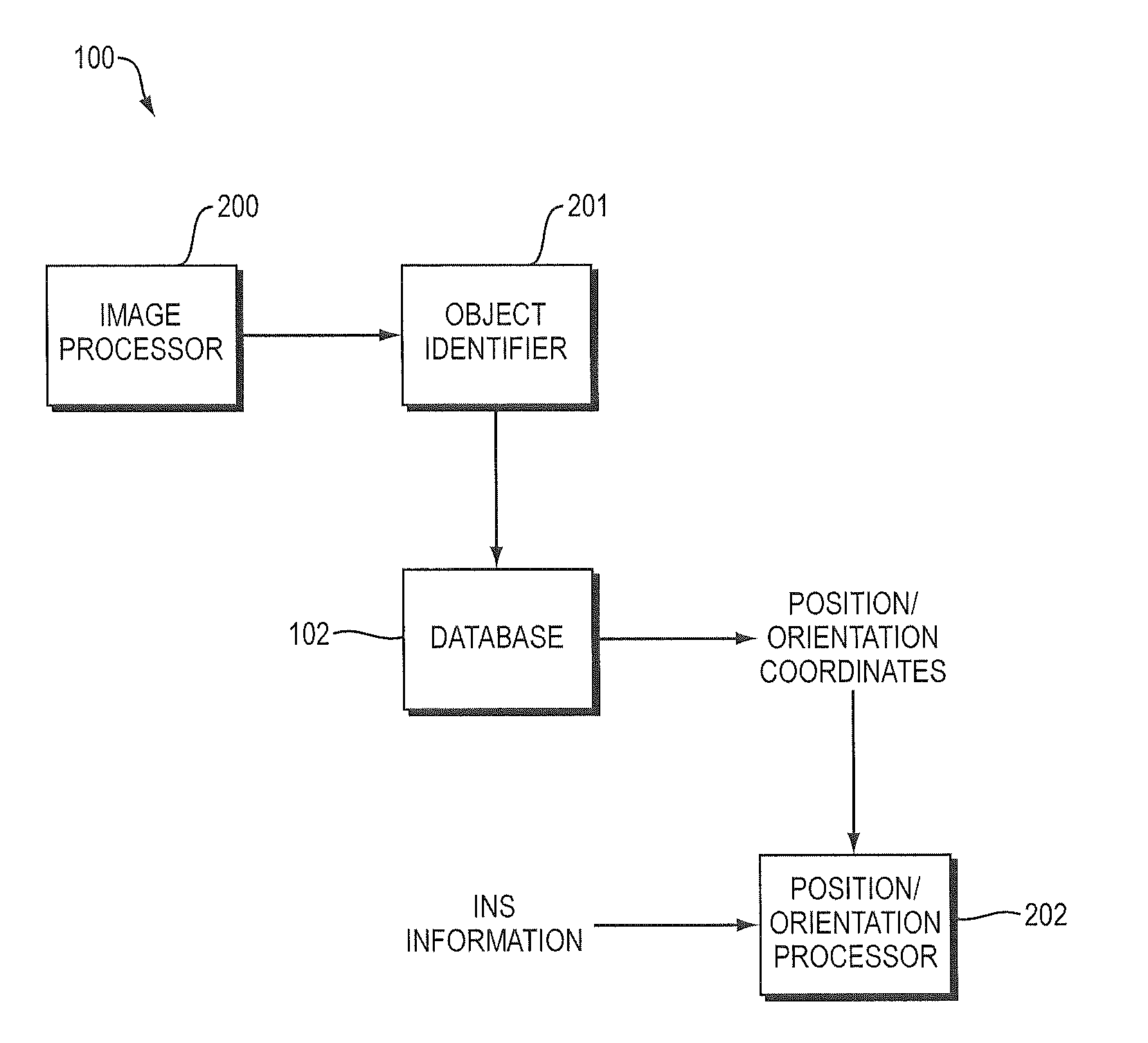
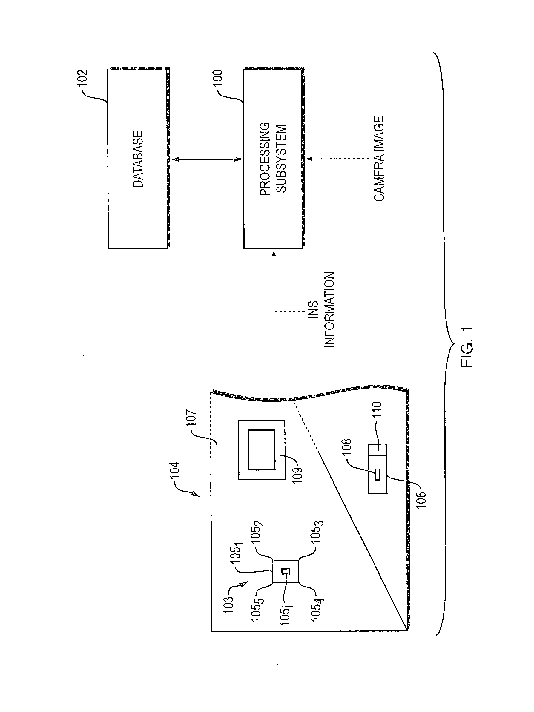
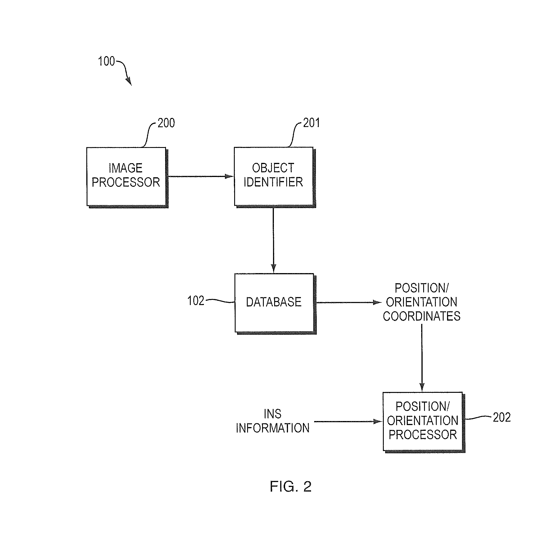
[0014]The system described below includes a data base that is available to multiple users of the system and which incorporates contributions from the multiple users of the system. As described in more detail below, the data base contains and / or is updated to contain object identification information and associated position coordinates, and as appropriate, orientation information, for uniquely identifiable objects in a working environment. The system may then determine the relative position and orientation of a camera operating in the environment based solely on images taken by the camera. The system may also update the database as new unique objects or altered unique objects are identified in the images of the environment and / or as more precise position and orientation information is available for the objects contained in the database. The system may operate in an initially unknown environment and populate an empty database by providing object identification information and associat...


PUM


Abstract

A system determines an otherwise unknown position and orientation of a camera in a working environment, relative to an associated coordinate system, based on visually identifiable unique objects in images taken by the camera. The system utilizes a database that includes or may be updated to include position coordinates for unique objects of interest. The system identifies a plurality of objects within one or more images taken by the camera at a given location, and enters the database either to determine position coordinates for the respective identified objects or to add position coordinates to the data base for the respective identified objects, or both. The system may also update the database to include newly identified unique objects and objects that are altered between images, to determine position and orientation of the camera in a changing environment. Sensors may be included to add additional information relative to the position and orientation of the camera.

Description

BACKGROUND OF THE INVENTION[0001]1. Field of the Invention[0002]The invention relates generally to visual positioning systems and, more particularly, to visual positioning systems that utilize images of a working environment to determine position.[0003]2. Background Information[0004]Machine control systems may utilize global navigation satellite system (GNSS) receivers to determine the global position of machinery, and inertial and other sensors may be added to provide information relating to the orientation and movement of the machinery. The GNSS receivers and inertial and other sensors update the position and orientation information to aid a driver or a robotic control in navigating the machine to a desired location or along a desired route, and so forth. These systems work well in many, but not all, environments. For example, the GNSS receivers may not work well in environments that include multiple nearby sources of multipath signals and / or in environments without sufficiently c...

Claims


Application Information

Patent Timeline
IPC IPC(8): H04N7/18
CPCH04N7/18G01C21/20H04N2201/3254H04N1/32117H04N2201/3253H04N17/002H04N23/80
Inventor MORIN, KRISTIANKENNEDY, SANDY
Owner HEXAGON TECH CENT GMBH
Why Eureka
Try Eureka