Color separation system

a color separation and color technology, applied in the field of color separation systems, can solve the problems of affecting application, high cost, and energy loss of 60-70% incident light, and achieve the effect of increasing light energy utilization efficiency

Inactive Publication Date: 2014-05-01
NATIONAL TSING HUA UNIVERSITY
View PDF12 Cites 0 Cited by
  • Summary
  • Abstract
  • Description
  • Claims
  • Application Information

AI Technical Summary

Benefits of technology

[0006]The present invention provides a color separation system, which uses a plurality of arrayed light source modules to generate light beams having different colors and separated spatially, and which uses a light guide module and an optical lens array to project the light beams having different colors to the display panel of an LCD device in an arrayed form, whereby the color separation system avoids using an absorption-type color filter, wherefore the present invention greatly increases the light energy utilization efficiency.

Problems solved by technology

However, the absorption-type color filter causes energy loss of about 60-70% incident light aboutwith 60-70%.energy.
However, high precision fabrication, high accuracy assemblage assembly and high cost required by these schemes are likely to hinder the application thereof.

Method used


Image

  • Color separation system
  • Color separation system
  • Color separation system

Examples


Embodiment Construction

[0014]The detailed explanation of the present invention is described as follows. The described preferred embodiments are presented for purposes of illustrations and description, and they are not intended to limit the scope of the present invention.

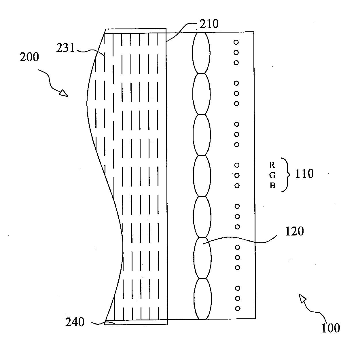
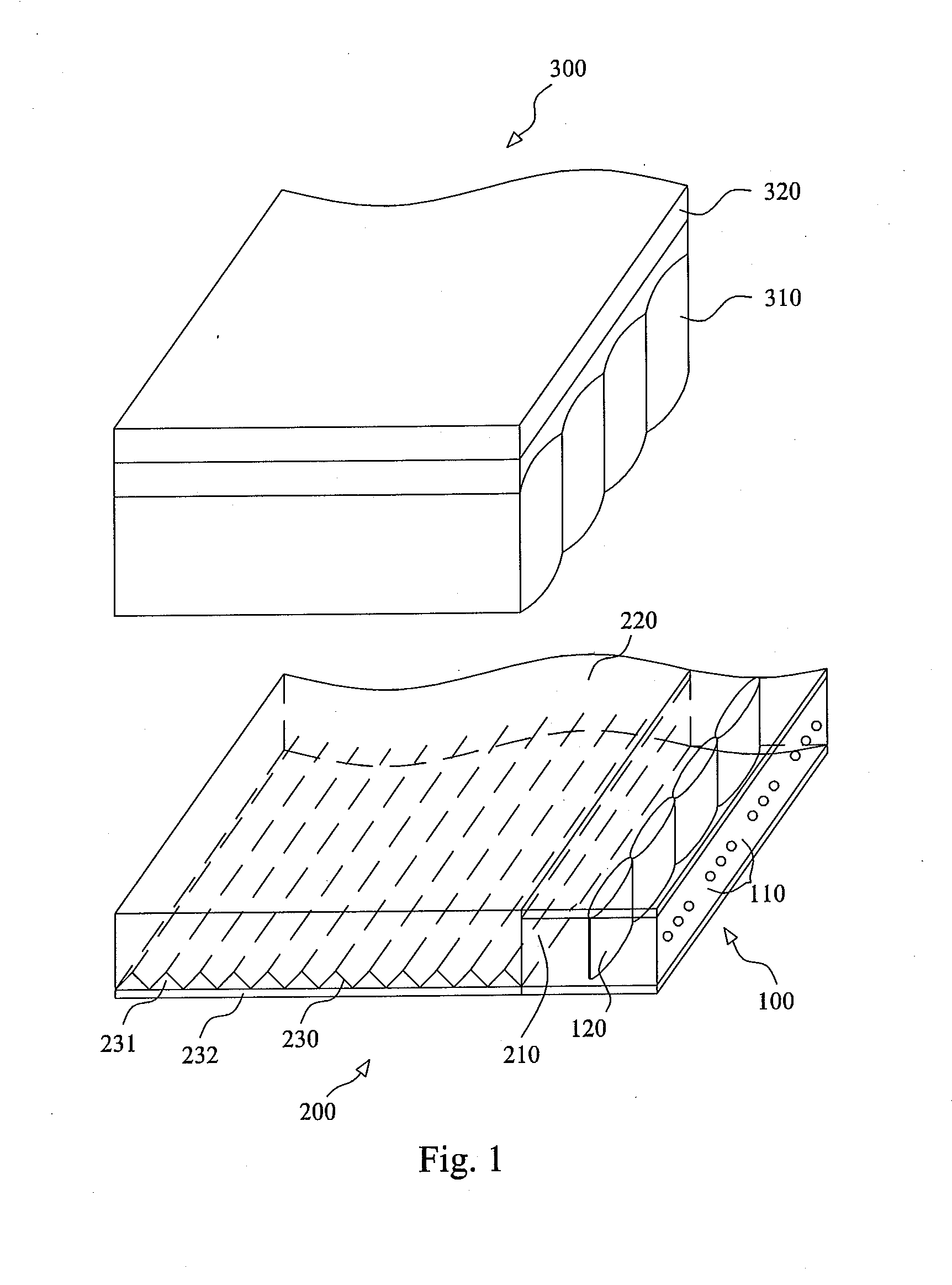
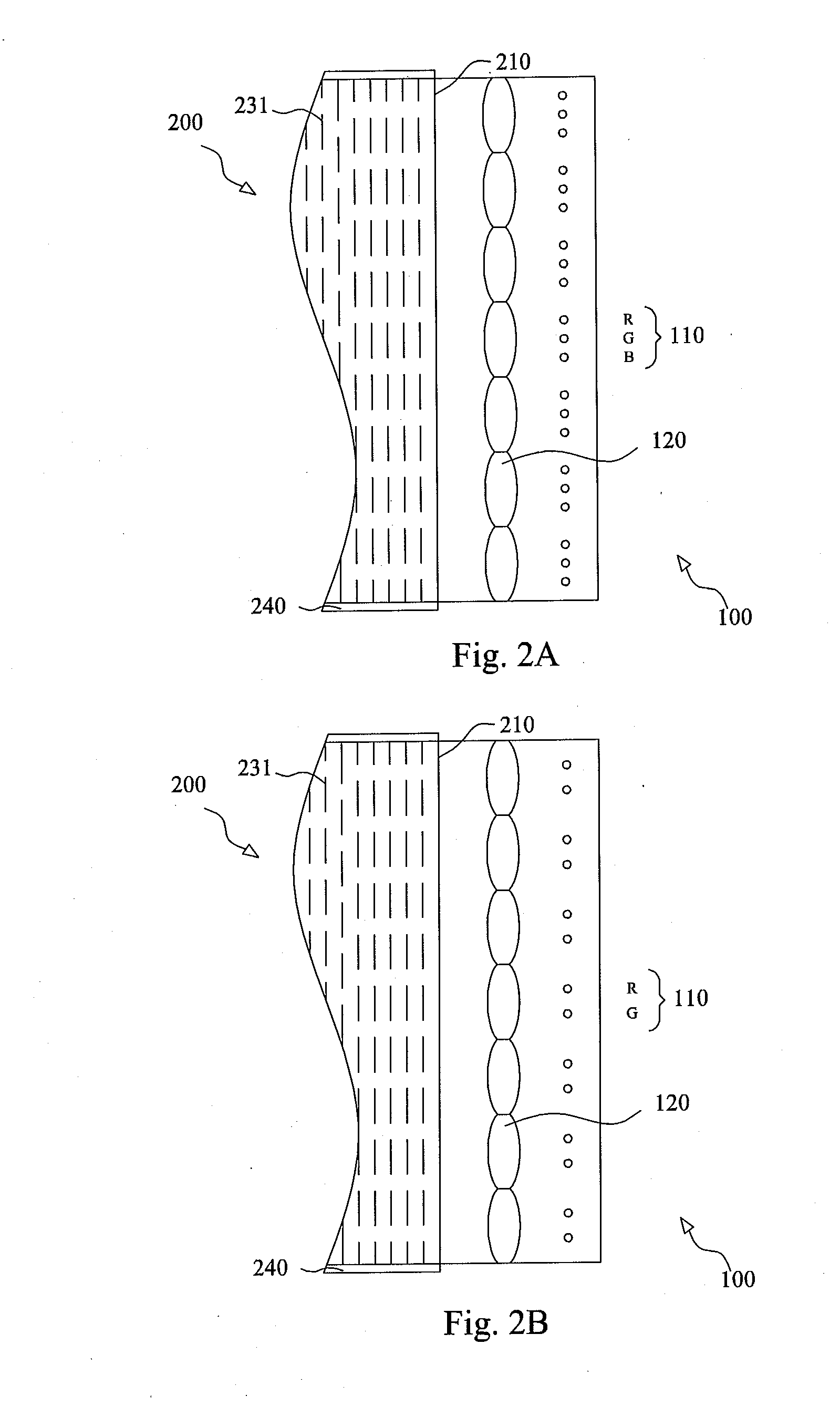
[0015]Refer to FIG. 1 schematically showing the structure of a color separation system according to one embodiment of the present invention. The color separation system of the present invention comprises a plurality of light source modules 100 arranged in array, a light guide module 200, and an optical lens array 300. Each light source module 100 includes a plurality of light emitting elements 110 emitting a plurality of light beams respectively having different central wavelengths and separated spatially, and an alignment lens 120 aligning the plurality of light beams L (shown in FIG. 3). The light guide module 200 includes a light incident face 210, a light exit face 220 and a bottom face 230. The bottom face 230 is opposite to the light...


PUM

PropertyMeasurementUnit
central wavelengthsaaaaaaaaaa
microstructureaaaaaaaaaa
displacementaaaaaaaaaa

Abstract

The present invention discloses a color separation system, which uses a plurality of arrayed light source modules to generate light beams having different colors and separated spatially, and which uses a light guide module and an optical lens array to project the light beams having different colors to the display panel of an LCD device in an arrayed form, whereby the color separation system is exempted from using an absorption-type color filter, wherefore the light energy utilization rate is greatly increased. Further, the present invention arranges a reflection-type polarization element on the light output side of the optical lens array and arranges a quarter-wave plate on the bottom face of the light guide module to replace the conventional absorption-type polarization element. Thus, the light energy utilization rate is further increased. Therefore, the present invention can save energy effectively.

Description

BACKGROUND OF THE INVENTION[0001]1. Field of the Invention[0002]The present invention relates to a color separation system, particularly to a color separation system free of an absorption-type color filter.[0003]2. Description of the Prior Art[0004]In order to display colored images, the conventional LCD (Liquid Crystal Display) device adopts the absorption-type color filter to separate the white light, which comes from the backlight module, into red, green and blue light beams. However, the absorption-type color filter causes energy loss of about 60-70% incident light aboutwith 60-70%.energy. Besides, the absorption-type polarization plate absorbs about 50% of light energy. The two abovementioned factors obviously lower the total light energy utilization rate of the LCD device. Under the trend of environmental protection and energy saving, increasing the light energy utilization rate has become an important topic. Many schemes have been proposed to replace the absorption-type color...

Claims


Application Information

Patent Timeline
Patent Type & Authority Applications(United States)
IPC IPC(8): G02F1/1335
CPCG02F1/1335G02F1/133621G02B6/003G02B6/0038G02B6/0056G02B6/0068
Inventor CHEN, CHENG-HUANYAO, PO-HUNG
Owner NATIONAL TSING HUA UNIVERSITY
Why Eureka
Try Eureka