Speaker device

a technology for speakers and auxiliary components, applied in the direction of electrical transducers, earpiece/earphone attachments, transducer details, etc., can solve the problem that the structure has a structural limit in responding to a request, and achieve the effect of reducing the distortion of the coil, and improving the quality of the driving sound

Active Publication Date: 2014-05-01
TOKYO ONKYO CO LTD
View PDF8 Cites 7 Cited by
  • Summary
  • Abstract
  • Description
  • Claims
  • Application Information

AI Technical Summary

Benefits of technology

[0035]According to the speaker device of the present invention, the vibrating film supported in the body frame is vibrated and driven by the first driving unit disposed on one surface side of the vibrating film, and is driven in the same direction as the first driving unit, by the second driving unit disposed on the other surface side of the vibrating film. Therefore, the higher quality and higher output of the driving sound can be achieved.
[0036]According to the speaker device of the present invention, the first driving unit has the first yoke disposed to face the central area of the vibrating film on one surface side of the vibrating film; the first magnet disposed in the first yoke so as to face the central area of the vibrating film; and the first coil fixed to the vibrating film and inserted into the outer periphery of the first magnet, with a slight space provided between them, and the second driving unit has a ring-shaped second yoke disposed to face the outer peripheral area of the vibrating film on the other surface side of the vibrating film; a ring-shaped second magnet disposed to face the outer peripheral area of the vibrating film on the vibrating film side of the second yoke; and the second coil fixed to the vibrating film on the other surface side of the vibrating film and inserted into the inner periphery of the second magnet, with a slight space provided between them. In the magnet structure with this structure, one sheet of vibrating film is driven by two coils of the first and second coils, to thereby reduce a distortion of the coils in an odd-order and realize the higher quality of the driving sound and also facilitate the higher output of the driving sound.
[0037]According to the speaker device of the present invention, the first and second coils are configured to drive the vibrating film based on the same voice signal in the same phase. With this structure, it is easy to apply the voice signal to the vibrating film.
[0038]According to the speaker device of the present invention, the first and second coils are configured to be same having the same shape, and are fixed to both surfaces of the vibrating film. With this structure, there is little variation in driving the vibrating film by the first and second driving units, and higher sound quality can be secured.
[0039]According to the speaker device of the present invention, the first and second magnets are mutually magnetized in the heteropolarity on the side facing the vibrating film, and the first yoke has the annular outer wall extending to the vicinity of the tip of the vibrating film of the first magnet with the first coil interposed between them, and the second yoke has the annular inner wall extending to the vicinity of the tip of the vibrating film of the second magnet with the second coil interposed between them. With this structure, leakage magnetic flux froth the first and second magnets is reduced, and magnetic flux density is improved, to thereby realize higher driving power and easily obtain higher sound quality.
[0040]According to the speaker device of the present invention, the lead wires of the first and second coils are formed so as to be led out diagonally on one surface side and the other surface side of the vibrating film, to thereby apply the voice signal to the first and second coils. With this structure, stress added on the vibrating film is dispersed, and the higher quality sound can be easily secured.

Problems solved by technology

Probably this structure has a structural limit in responding to a request of a user such as a higher quality and higher output of a driving sound.

Method used


Image

  • Speaker device
  • Speaker device
  • Speaker device

Examples


Embodiment Construction

[0049]Embodiments of a speaker device according to the present invention will be described hereafter, with reference to the drawings.

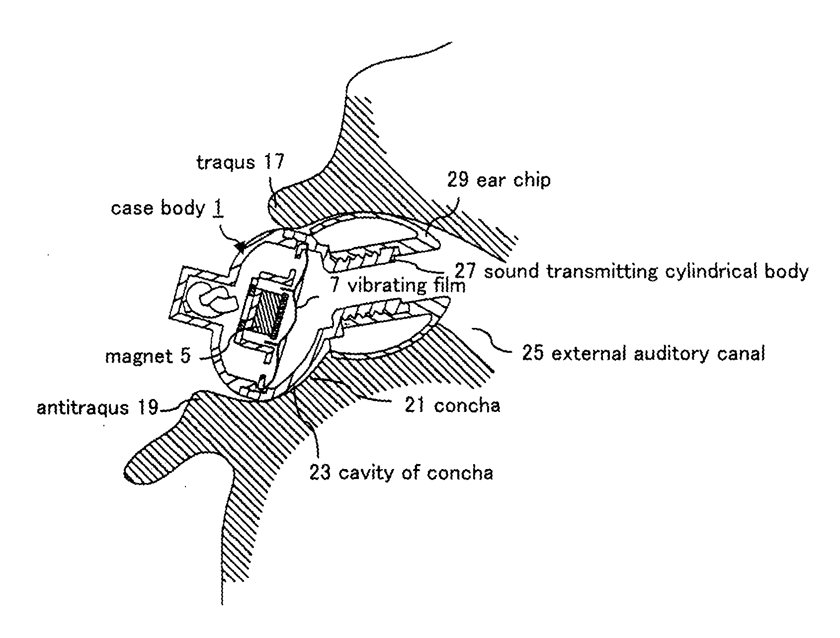
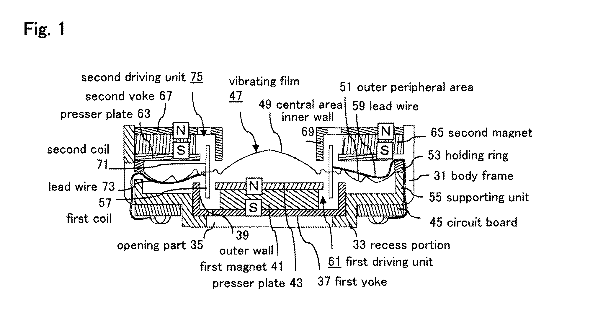
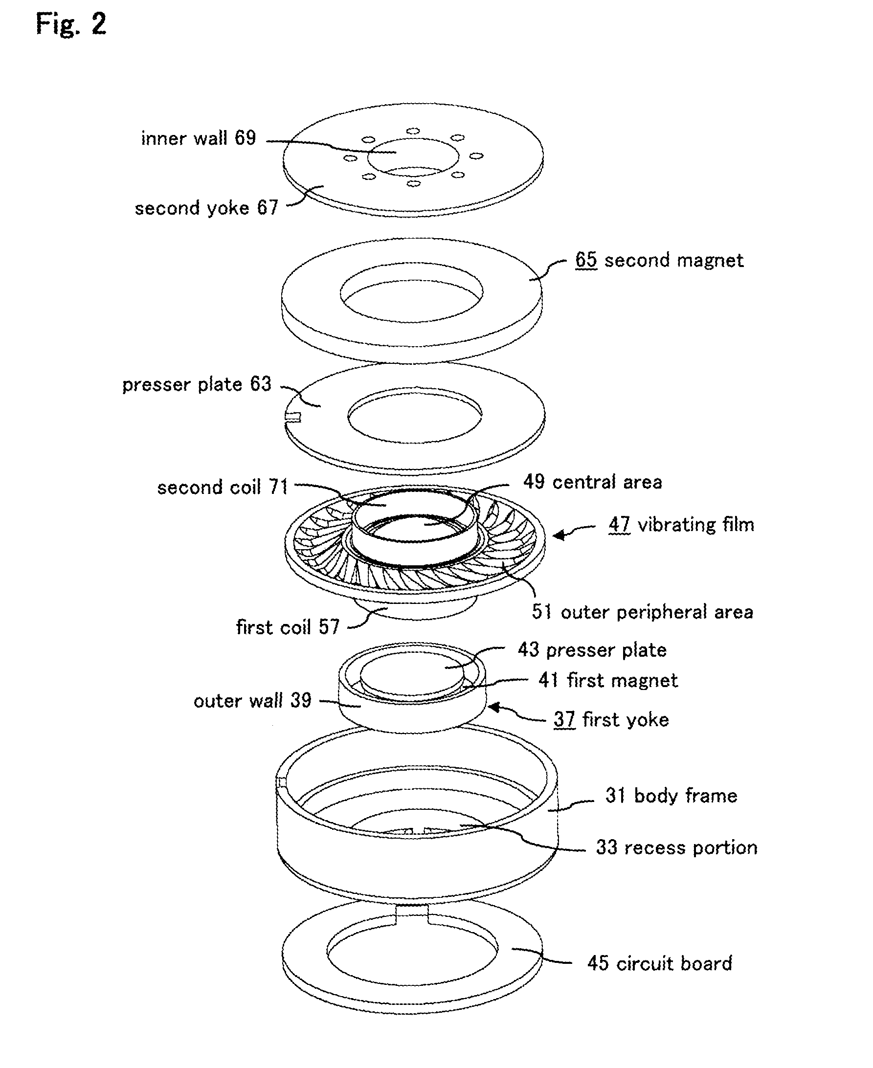
[0050]FIG. 1 and FIG. 2 are cross-sectional view and a developed perspective view of an essential part, showing the speaker device according to an embodiment of the present invention, with an earphone device taken as an example.

[0051]In FIG. 1 and FIG. 2, a body frame 31 is formed into a cylindrical shape with a bottom, which is made of insulating synthetic resin, and has a recess portion 33 on a bottom part. An opening part 35 is formed in this recess portion 33.

[0052]The first yoke 37 is formed into a cup-shape, made of a magnetic material, and is fixed to an inside of the recess portion 33 of the body frame 31, with an opening part disposed at an upper side in the figure. Reference number 39 indicates an annular outer wall extending to the vicinity of a vibrating film 47 described later from an outer peripheral edge of the first yoke 37.

[0053]One en...


PUM


Abstract

A vibrating film 47 is supported by a cylindrical body frame 31, and a first driving unit 61 for driving the vibrating film 47 based on an applied voice signal, is disposed in the body frame 31 on one surface side of the vibrating film 47, and a second driving unit 75 for driving the vibrating film 47 in the same direction as a vibrating direction of the vibrating film 47 driven by the first driving unit 61 based on the applied voice signal, is disposed in the body frame 31 on the other surface side of the vibrating film 47.

Description

BACKGROUND[0001]1. Technical Field[0002]The present invention relates to a speaker device, and relates to an improvement of the speaker device suitably used for an earphone device such as an earphone or a headphone, etc., for example, which is worn in an ear of a user.[0003]2. Description of Related Art[0004]Conventionally, for example a structure shown in FIG. 6 is known as the earphone device worn in the ear of the user. In this structure, one of the end faces of a cylindrical magnet 5 is fixed to an inside of a cup-shaped yoke 3 disposed in a case body 1; a thin vibrating film 7 is fixed to a tip of the yoke 3 to thereby cover an opening part of the yoke 3; the vibrating film 7 and the other end face of the magnet 5 are disposed to face each other; and a cylindrical coil 9 fixed to the vibrating film 7, is inserted into an outer periphery of the magnet 5, with a slight space provided between them.[0005]In FIG. 6, the case body 1 is composed of a funnel-shaped base part 1a and a f...

Claims


Application Information

Patent Timeline
Patent Type & Authority Applications(United States)
IPC IPC(8): H04R1/10
CPCH04R1/1058H04R9/06H04R1/1016H04R1/1075H04R9/025
Inventor TANAKA, KENTA
Owner TOKYO ONKYO CO LTD
Why Eureka
Try Eureka