Accelerator pedal apparatus for vehicle

a pedal apparatus and accelerator technology, applied in the direction of mechanical control devices, process and machine control, instruments, etc., can solve the problem that the pedal effort cannot be adjusted

Inactive Publication Date: 2014-05-08
HYUNDAI MOTOR CO LTD
View PDF2 Cites 6 Cited by
  • Summary
  • Abstract
  • Description
  • Claims
  • Application Information

AI Technical Summary

Benefits of technology

[0012]The present invention has been made in an effort to solve the above-described problems associated with prior art, and it relates to providing an accelerator pedal apparatus for a vehicle through which pedal effort and stroke of the pedal can be adjusted in accordance with a driving condition, a driver condition and driving inclination of a driver, and which can be applied commonly to various kinds of vehicles.

Problems solved by technology

However, in the accelerator pedal apparatus according to the related art, since the spring 6 set in advance with an elastic coefficient to meet international safety regulations has to be used, the pedal effort cannot be adjusted unless the spring is replaced with new one.

Method used


Image

  • Accelerator pedal apparatus for vehicle
  • Accelerator pedal apparatus for vehicle
  • Accelerator pedal apparatus for vehicle

Examples


Embodiment Construction

[0029]Hereinafter, an accelerator pedal apparatus for a vehicle according a preferred embodiment of the present invention will be described referring to the accompanying drawings.

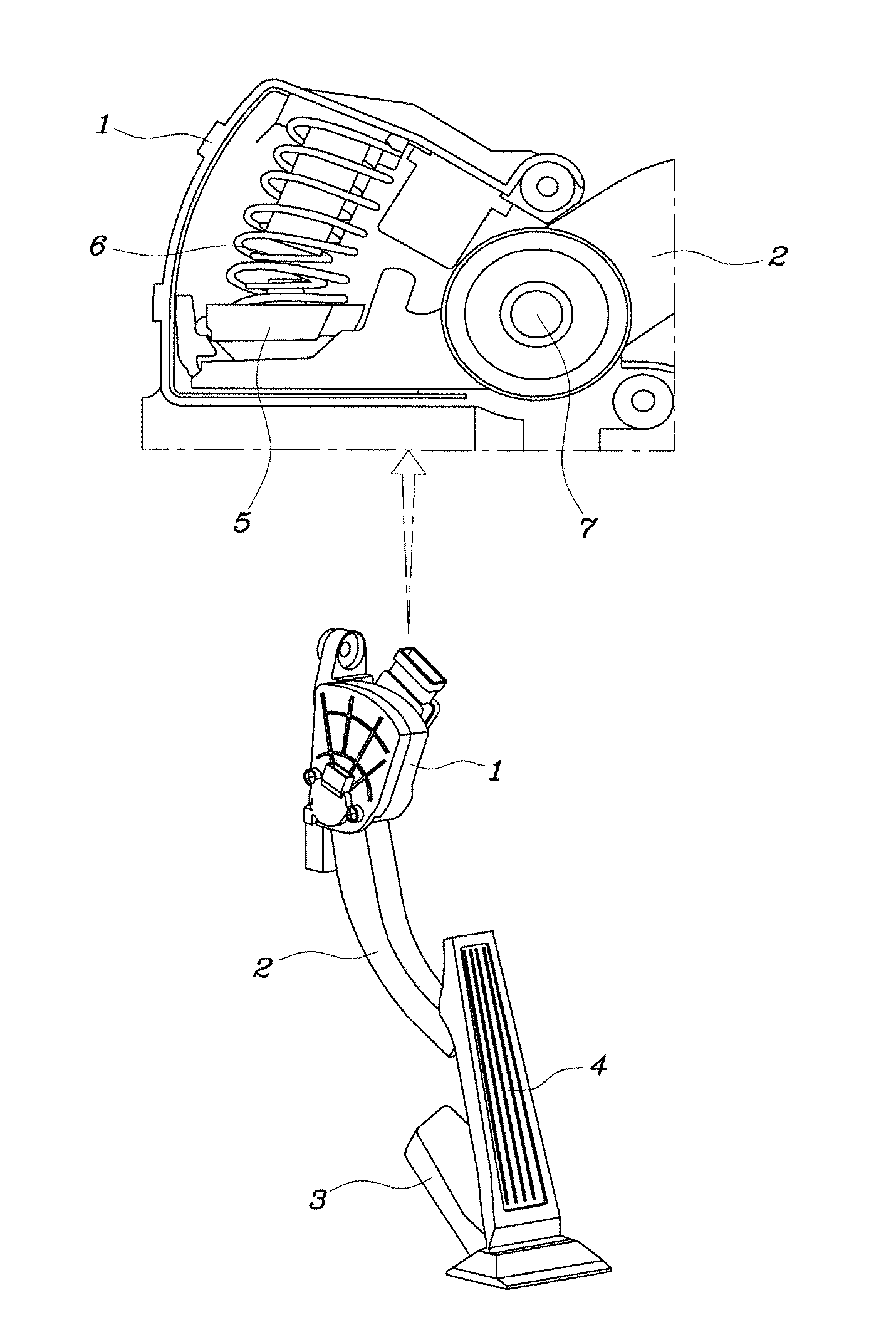
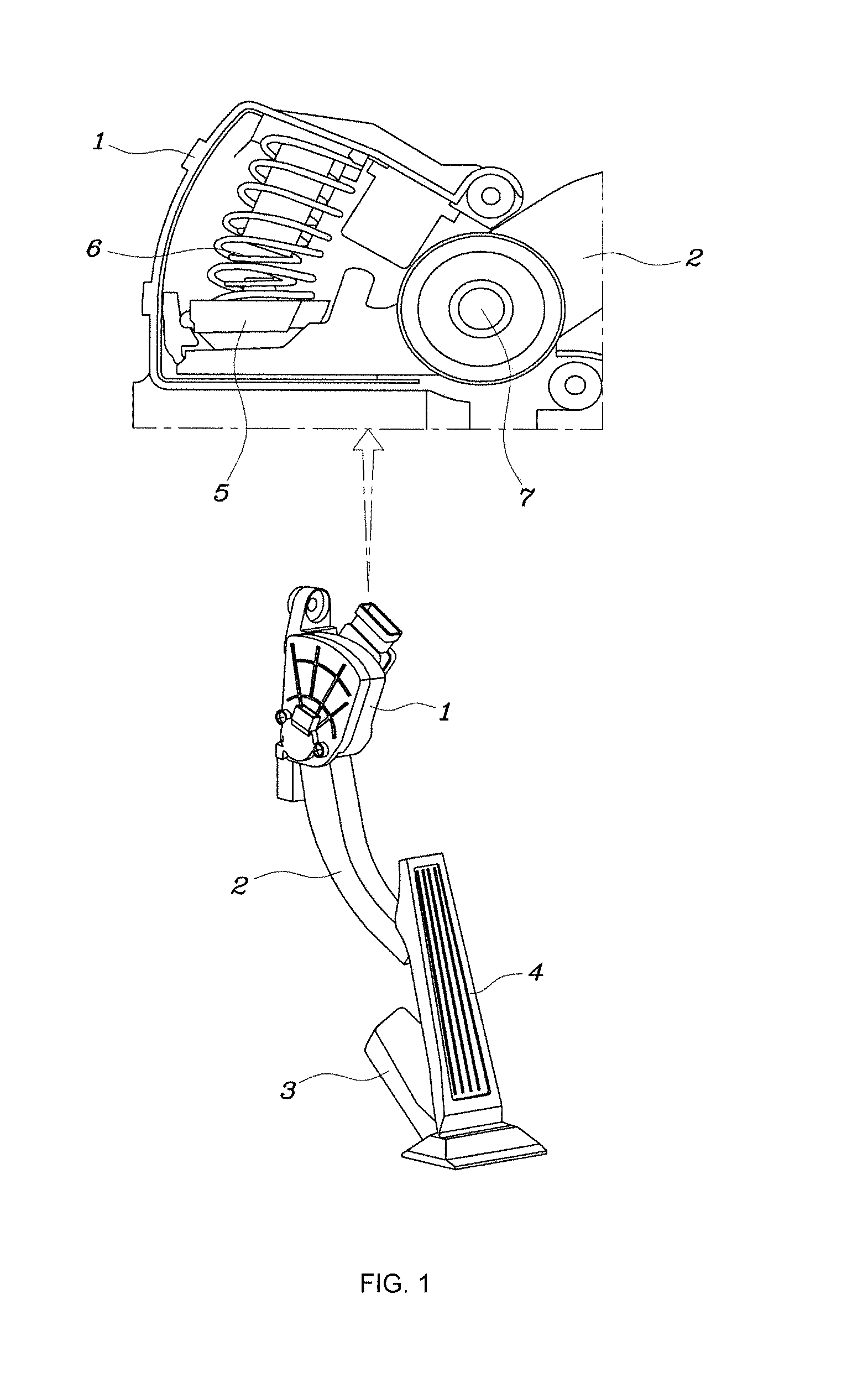
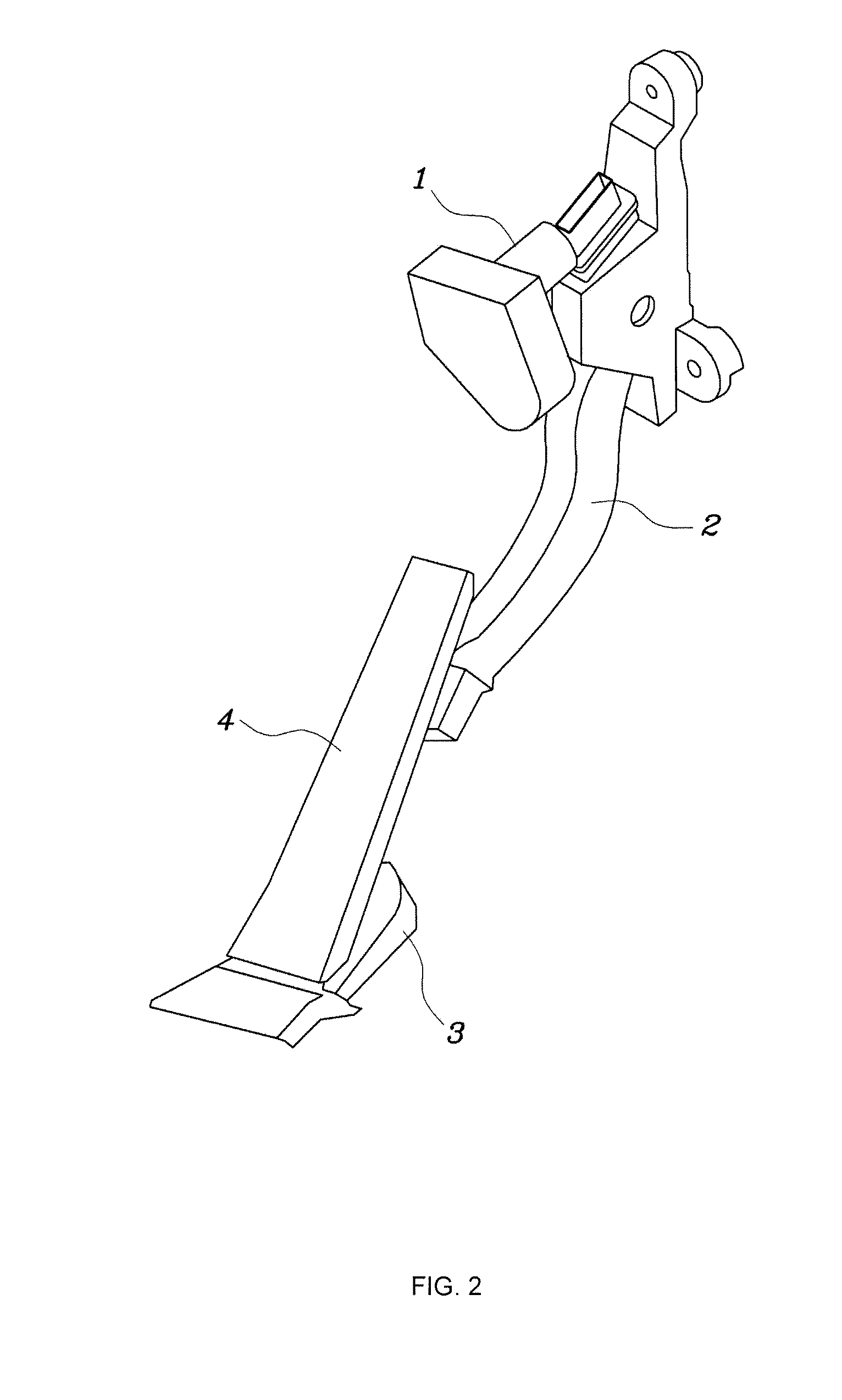
[0030]The accelerator pedal apparatus for a vehicle according to the present invention, as shown in FIGS. 2 to 8, may include a pedal arm housing 1 that is fixed to a vehicle body panel at a lower part of a driver seat, a pedal arm 2 one end of which is coupled rotatably to the pedal arm housing 1, a pedal bracket 3 that is fixed to a floor panel at a lower part of the driver seat, and a pedal pad 4 one end of which is hinge-coupled rotatably to the pedal bracket 3 and which is ball-jointed to the pedal arm 2.

[0031]Meanwhile, a spring plate 5, (FIG. 3) is coupled to one end of the pedal arm 2 disposed inside the pedal arm housing 1 and the pedal arm 2 rotates with respect to the pedal arm housing 1 through a hinge shaft 7.

[0032]The accelerator pedal apparatus according to the present invention may include a...


PUM


Abstract

An accelerator pedal apparatus, in which pedal effort can be varied through length variation of a spring. Stroke of a pedal arm can be varied in accordance with inclination and body type of driver.

Description

CROSS-REFERENCE TO RELATED APPLICATION[0001]This application claims under 35 U.S.C. §119(a) the benefit of Korean Patent Application No. 10-2012-0126283 filed on Nov. 8, 2012, the entire contents of which are incorporated herein by reference.BACKGROUND[0002](a) Technical Field[0003]The present disclosure relates to an accelerator pedal apparatus for a vehicle, and more particularly, to an accelerator pedal apparatus for a vehicle in which pedal effort and a stroke of the pedal can be adjusted.[0004](b) Background Art[0005]FIG. 1 is a perspective view illustrating an accelerator pedal apparatus for a vehicle of an organ type according to related art wherein it includes a pedal arm housing 1 that is fixed to a vehicle body panel at a lower part of a driver seat, a pedal arm 2 one end of which is coupled rotatably to the pedal arm housing 1, a pedal bracket 3 that is fixed to a floor panel at a lower part of the driver seat, and a pedal pad 4 one end of which is hinge-coupled rotatably...

Claims


Application Information

Patent Timeline
Patent Type & Authority Applications(United States)
IPC IPC(8): G05G1/30
CPCG05G1/30G05G5/03Y10T74/20534B60K26/00B60K26/02
Inventor KIM, EUN SIKCHO, YANG RAEMIN, JEONG SEONLEE, KWANG GI
Owner HYUNDAI MOTOR CO LTD
Why Eureka
Try Eureka