Flow deflecting member for hydrocyclone

a technology of hydrocyclones and members, applied in the direction of centrifugal force sediment separation, filtration separation, moving filter elements, etc., can solve the problems of increasing the amount of rejected fibres, increasing the risk of operation problems, and increasing the cost of fibre reject losses

Active Publication Date: 2014-05-08
OVIVO LUXEMBOURG R L
View PDF0 Cites 10 Cited by
  • Summary
  • Abstract
  • Description
  • Claims
  • Application Information

AI Technical Summary

Benefits of technology

[0012]An object of the present invention is to alleviate the disadvantages of the prior art and to provide an improved hydrocyclone for separating a liquid mixture into a heavy fraction including heavy particles, and a light fraction.

Problems solved by technology

However, this will at the same time increase the amount of rejected fibres that settles towards the hydrocyclone wall.
A high Tf is not wanted as it greatly increases the risk of operational problems including fibres blocking the reject outlet, high fiber losses towards the reject outlet, locally higher fibre consistencies resulting in fibre networks or flocks that traps the heavy particles that is to be separated.
A high Tf will further result in higher costs due the fibre reject losses or alternatively, in an aim to resolve the problem, due to higher energy and investment costs by using cascade coupled hydrocyclones for fibre recovery purposes.
Such means for creating turbulence may be a step where the radius of the inside wall of the separation chamber suddenly increases, which causes a turbulent flow expanding flocks of fibres and releasing undesired particles from the fibre network often forming close to the wall of the separation chamber.
Due to the sudden increase of the radius in EP615469 there is a substantial risk that the already separated heavy particles are again remixed with the light fraction.
Although these guide bars have a decreasing radius in the separation chamber, their extensive lengths in an axial direction disturb the helical vortex and the separation efficiency is decreased.
Additionally, the fact that the guide bars are axially oriented and lack any components in the direction of the liquid stream further prevents the hydrocyclones capability to transport the heavy particles towards the reject outlet.

Method used


Image

  • Flow deflecting member for hydrocyclone
  • Flow deflecting member for hydrocyclone
  • Flow deflecting member for hydrocyclone

Examples


Embodiment Construction

[0044]In the following, a detailed description of the invention is presented.

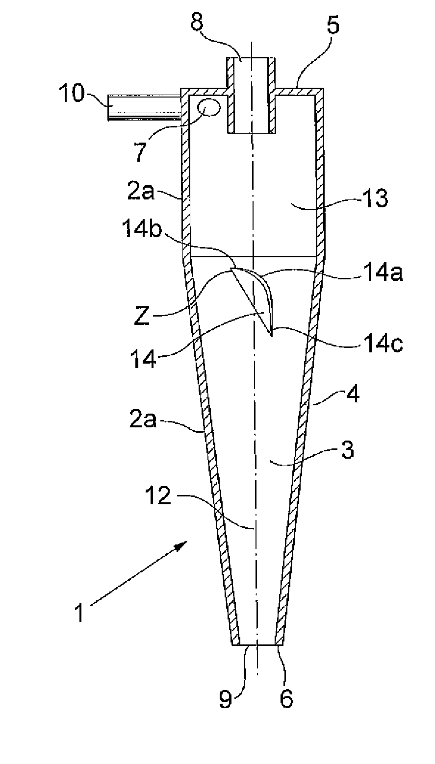
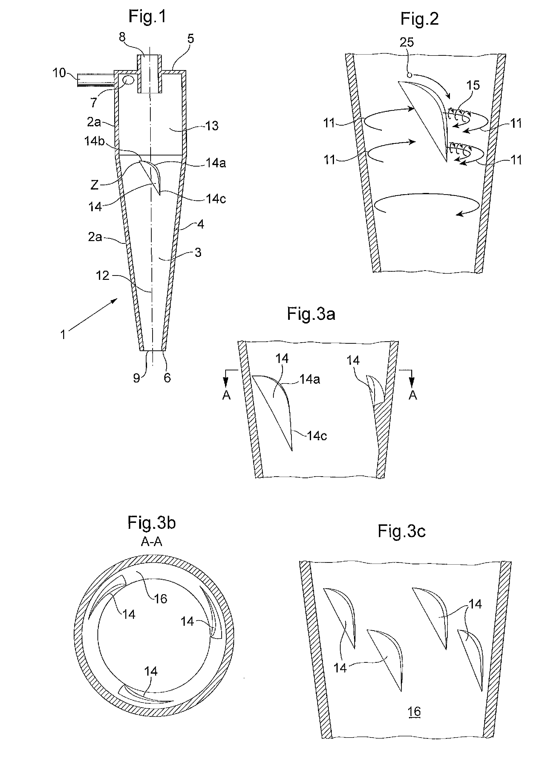
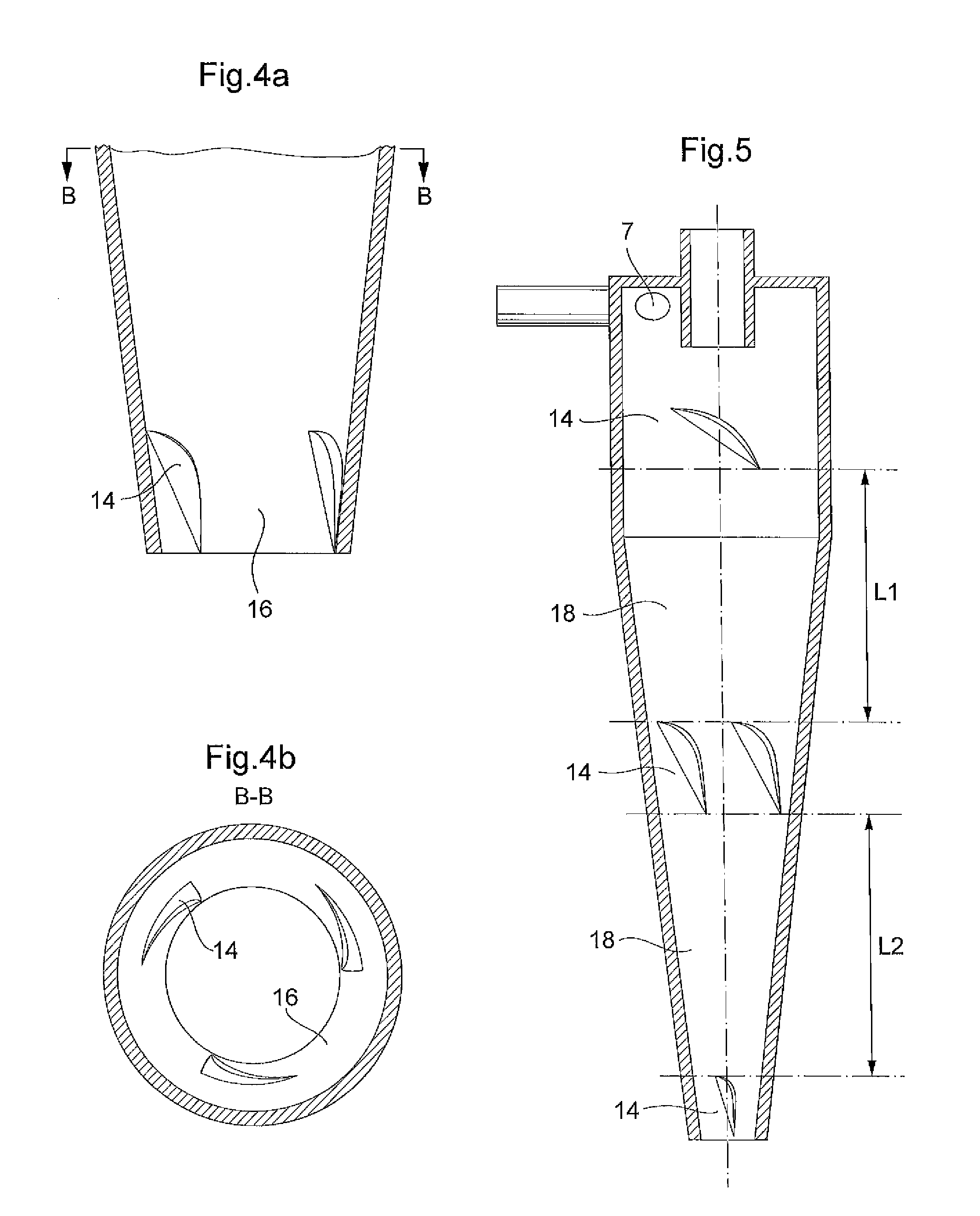
[0045]FIG. 1 shows a hydrocyclone 1 for separating a liqid mixture into a heavy fraction and a light fraction in a sectional view along a centre axis 12. The hydrocyclone 1 comprises a housing 2 forming an elongated separation chamber 3 having a smooth circumferential wall 4. Further, as presented in FIG. 1, the housing 2 may consist of a cylindrically shaped portion 2a, and a conical portion 2b. The hydrocyclone 1 has a base end 5 wherein an inlet member 7 is arranged via which a liquid mixture to be separated will be supplied preferably tangentially into the separation chamber 3 by means 10 for this purpose, such as a pump, in order to generate a liquid stream in the form of a helical vortex 11 about the centre axis 12. If desired, several inlet members may be arranged, for example one arranged at about the middle of the length of the hydrocyclone 1 (not shown).

[0046]The hydrocyclone 1 comprises an apex e...


PUM

PropertyMeasurementUnit
angleaaaaaaaaaa
angleaaaaaaaaaa
angleaaaaaaaaaa

Abstract

A hydrocyclone (1) for separating a liquid mixture into a heavy fraction including heavy particles and alight fraction, comprising a housing (2) forming an elongated separation chamber (3) having a circumferential wall (4), abase end (5),an apex end (6), at least one inlet member (7) for supplying a liquid mixture into the separation chamber (3), at least one of the inlet member / s(7) positioned at the base end (5), a first outlet member (8) for discharging separated light fraction from the separation chamber (3) at the base end (5), a second outlet member (9) for discharging separated heavy fraction from the separation chamber (3) at the apex end (6), means (10) for supplying the liquid mixture to the separation chamber (3) via the at least one inlet member (7), so that during operation a liquid stream is generated as a helical vortex (11) about a centre axis (12) in the separation chamber (3), said helical vortex (11) extending from the base end (5) to the apex end (6), a first flow deflection means arranged in the circumferential wall (4) which comprises at least one member (14) in the path 13 of the liquid stream showing a decrease of the radius of the separation chamber, followed by an increase of the radius of the separation chamber,where in the at least one member comprises a rounded curve portion 14a for transporting the heavy 14c particles.

Description

TECHNICAL FIELD[0001]The present invention concerns a hydrocyclone with flow deflection means for creating a controlled turbulence and avoiding re-mixing of separated heavy particles into an accept stream of light accept fibres. In more detail, a hydrocyclone for separating a liquid mixture in a heavy fraction and a light fraction, comprising a housing forming an elongated separation chamber having a circumferential wall, a base end and an apex end. The housing having at least one inlet member for supplying a liquid mixture into the separation chamber where at least one of the inlet member / -s is positioned at the base end, at least one first outlet member for discharging separated light fraction from the separation chamber at the base end, and a second outlet member for discharging separated heavy fraction from the separation chamber at the apex end.[0002]It is also provided means for supplying the liquid mixture to the separation chamber via the at least one inlet member, so that d...

Claims


Application Information

Patent Timeline
Patent Type & Authority Applications(United States)
IPC IPC(8): B04C5/081B04C5/103
CPCB04C5/103B04C5/081D21D5/24B01D17/0217B01D21/267B04C5/107
Inventor BACHMAN, JANKUCHER, VALENTINATIDBECK, BJORN
Owner OVIVO LUXEMBOURG R L
Why Eureka
Try Eureka