
Winding switching circuit and thermal protection for dual voltage hermetic induction motor of hermetic cooling compressor

Inactive Publication Date: 2014-05-08
WHIRPOOL SA
View PDF9 Cites 5 Cited by
  • Summary
  • Abstract
  • Description
  • Claims
  • Application Information

AI Technical Summary

Benefits of technology

[0017]An objective of the invention is to provide a winding switching circuit and thermal protection for dual voltage induction motors that are suited for use in hermetic compre

Problems solved by technology

For voltage variations in excess of 10%, it is not possible to use the same project, and a new windings arrangement must be used for this voltage.
Another factor which hampers the use of a same windings circuit project for a broad range of voltages is the specification of the other electrical components such as capacitors, relays, thermal protectors, etc., which are normally sized to function inside a limited voltage variation, and may lose the functionality when submitted to voltages outside this range.
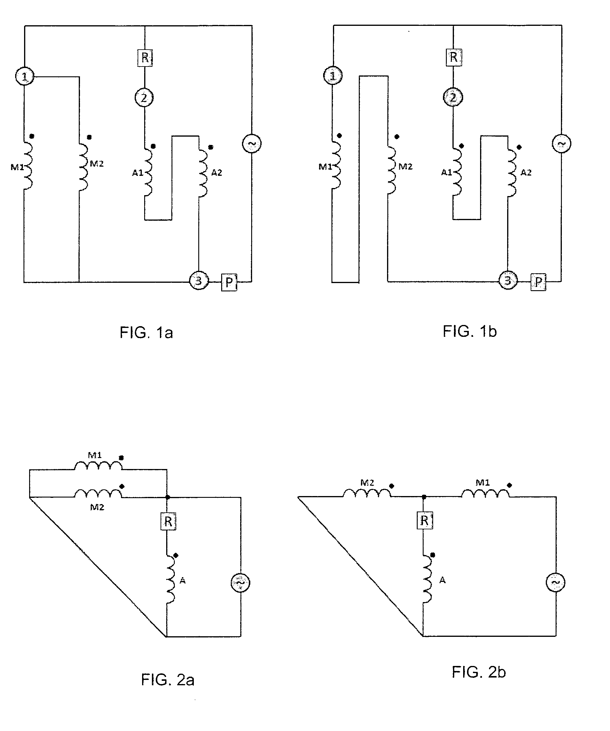
However, in motors for hermetic compressors, the access to the compressor terminals is limited, being normally by way of a hermetic 3-pin terminal.
This hampers the application of T-connection circuits, as there is no possibility of independent access to the terminals of the windings M1 and M2, unless a new terminal with a greater number of pins is used.
There is therefore no type of arrange

Method used


Image

  • Winding switching circuit and thermal protection for dual voltage hermetic induction motor of hermetic cooling compressor
  • Winding switching circuit and thermal protection for dual voltage hermetic induction motor of hermetic cooling compressor
  • Winding switching circuit and thermal protection for dual voltage hermetic induction motor of hermetic cooling compressor

Examples


Example

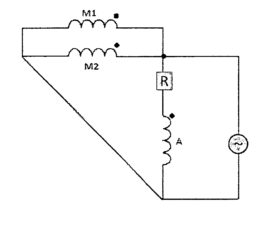
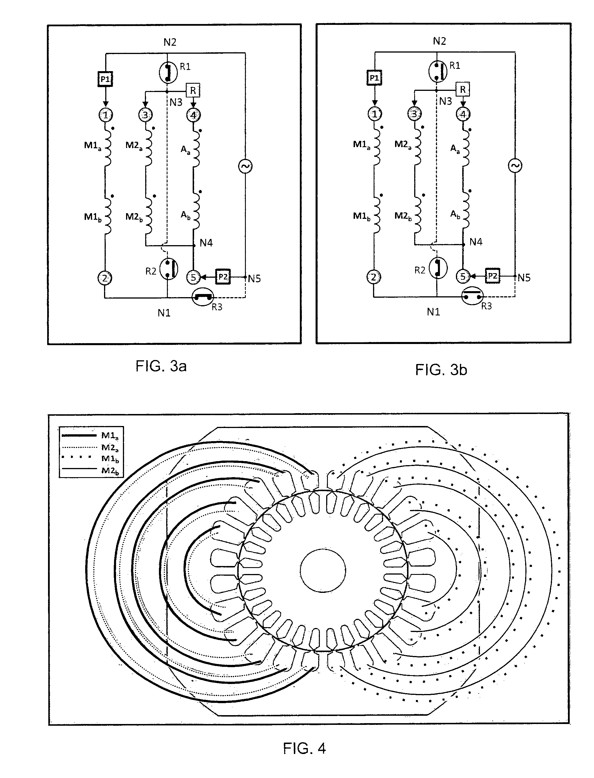
[0039]FIGS. 3A and 3B show a first embodiment of the arrangements of the winding switching circuit and thermal protection of the present invention respectively for power voltages of 115V and 220V. It should be noted that the same electric components are used in both arrangements, and it is only the electrical connections between the components that are changed from one arrangement to the other by means of switches that open and close.

[0040]The circuit according to the present invention uses five connection pins 1, 2, 3, 4, 5 in a hermetic terminal, instead of just the three pins used in the circuits of the state of the art. The circuit comprises a main winding with two coils M1 and M2, and an auxiliary winding A. In FIGS. 3A and 3B, each coil of the main winding M1 and M2 is represented by two independent coil parts, M1a M1b, M2a M2b, representing the two poles of the motor. The coil of the auxiliary winding is also represented the two independent coils Aa and Ab. The circuit also c...


PUM


Abstract

A winding switching circuit and thermal protection for dual voltage hermetic induction motors used in hermetic cooling compressors. The circuit includes two coils of the main winding, an auxiliary winding, three switches that are connected based on desired connections for each of the power arrangements, a start-up relay and thermal protection devices that protect the two main windings from overheating. The circuit is operative in first and second arrangements. In the first arrangement, the first switch and the third switch are connected, the second switch is disconnected, and the first main winding, and second main winding and the auxiliary winding are connected in parallel. In the second arrangement, the first switch and the third switch are disconnected, the second switch is connected, and the first main winding and the second main winding are connected in series and the auxiliary winding is connected in parallel only to the second main winding.

Description

[0001]The present invention refers to a winding switching circuit and thermal protection for single phase dual voltage induction motors, normally, used in hermetic compressors for cooling, which allows the motors to operate within the entire voltage range between approximately 90 and 260 V.DESCRIPTION OF THE STATE OF THE ART[0002]Single phase induction motors used in hermetic compressors for cooling are normally designed so as to enable them to be used in a limited voltage range. Typically, the design allows from 10% subvoltage to 10% overvoltage to be applied to the motor. This means that a motor designed for 115V should function without problems when a range of 103V to 127V is applied thereto. For voltage variations in excess of 10%, it is not possible to use the same project, and a new windings arrangement must be used for this voltage.[0003]Another factor which hampers the use of a same windings circuit project for a broad range of voltages is the specification of the other elec...

Claims


Application Information

Patent Timeline
IPC IPC(8): H02P25/18
CPCH02P25/188
Inventor KALLUF, FLAVIO J.H.DE ESPINDOLA, ALEANDRO AMAURI
Owner WHIRPOOL SA
Learn More