Led-based illumination module on-board diagnostics

a technology of led illumination module and diagnostics, which is applied in the field of led-based illumination module on-board diagnostics, can solve the problems of reducing the life of the led illumination device, reducing the life of the led, and requiring large amounts of heat sinking and specific power requirements

Active Publication Date: 2011-10-20
SBC XICATO CORP
View PDF5 Cites 132 Cited by
  • Summary
  • Abstract
  • Description
  • Claims
  • Application Information

AI Technical Summary

Problems solved by technology

Illumination devices that include LEDs typically require large amounts of heat sinking and specific power requirements.
Even partial failures with respect to heat sinking, power requirements, or any other system failures, such as degradation of phosphor, operating outside nominal operating conditions, LED failures, etc. can severely degrade performance.
However, once a conventional LED-based illumination device is installed it is difficult to access and, thus, problems associated with illumination device are typically not diagnosed or addressed resulting in degradation of performance and reduction in lifetime.

Method used


Image

  • Led-based illumination module on-board diagnostics
  • Led-based illumination module on-board diagnostics
  • Led-based illumination module on-board diagnostics

Examples


Embodiment Construction

[0047]Reference will now be made in detail to background examples and some embodiments of the invention, examples of which are illustrated in the accompanying drawings.

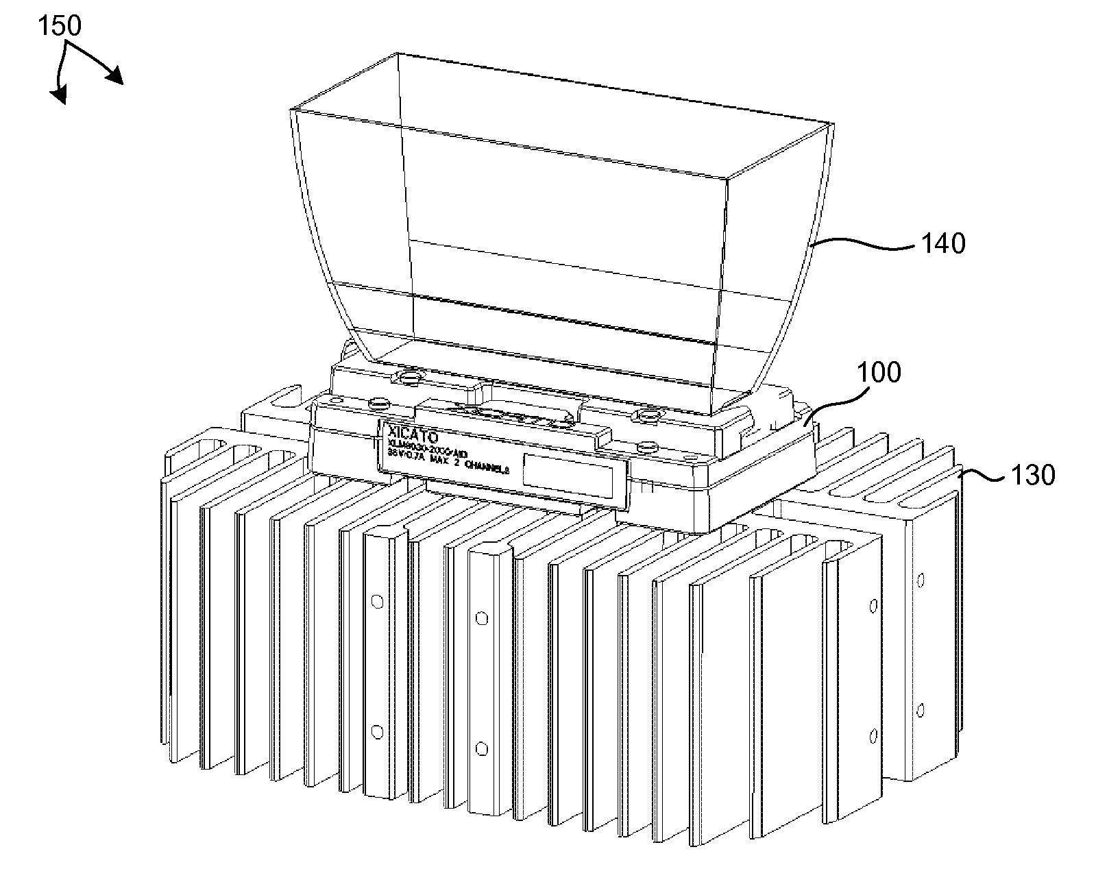
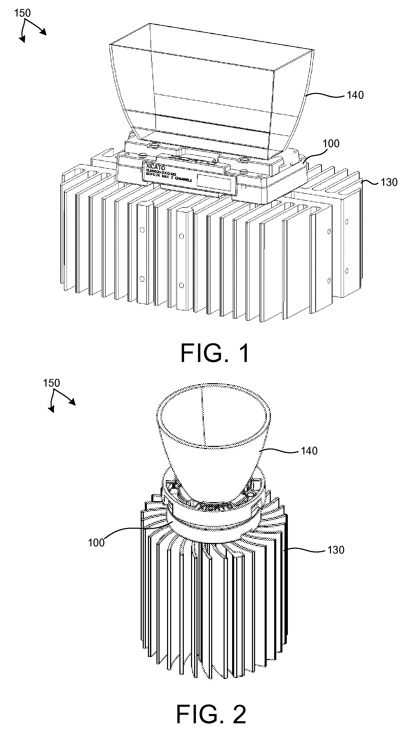
[0048]FIGS. 1-2 illustrate two exemplary luminaires. The luminaire illustrated in FIG. 1 includes an illumination module 100 with a rectangular form factor. The luminaire illustrated in FIG. 2 includes an illumination module 100 with a circular form factor. These examples are for illustrative purposes. Examples of illumination modules of general polygonal and elliptical shapes may also be contemplated. Luminaire 150 includes illumination module 100, reflector 140, and light fixture 130. As depicted, light fixture 130 is a heat sink and, thus, may sometimes be referred to as heat sink 130. However, light fixture 130 may include other structural and decorative elements (not shown). Reflector 140 is mounted to illumination module 100 to collimate or deflect light emitted from illumination module 100. The reflector 140 ma...


PUM


Abstract

A light emitting diode (LED) based illumination module performs on-board diagnostics. For example, diagnostics may include estimating elapsed lifetime, degradation of phosphor, thermal failure, failure of LEDs, or LED current adjustment based on measured flux or temperature. The elapsed lifetime may be estimated by scaling accumulated elapsed time of operation by an acceleration factor derived from actual operating conditions, such as temperature, current and relative humidity. The degradation of phosphor may be estimated based on a measured response of the phosphor to pulsed light from the LEDs. A thermal failure may be diagnosed using a transient response of the module from a start up condition. The failure of LEDs may be diagnosed based on measured forward voltage. The current for LEDs may adjusted using measured flux values and current values and a desired ratio of flux values. Additionally, the LED current may be scaled based on a measured temperature.

Description

CROSS REFERENCE TO RELATED APPLICATIONS[0001]This application claims the benefit of Provisional Application No. 61 / 356,525, filed Jun. 18, 2010, which is incorporated by reference herein in its entirety.TECHNICAL FIELD[0002]The described embodiments relate to illumination modules that include Light Emitting Diodes (LEDs).BACKGROUND INFORMATION[0003]The use of LEDs in general lighting is becoming more desirable and more prevalent. Illumination devices that include LEDs typically require large amounts of heat sinking and specific power requirements. Even partial failures with respect to heat sinking, power requirements, or any other system failures, such as degradation of phosphor, operating outside nominal operating conditions, LED failures, etc. can severely degrade performance. However, once a conventional LED-based illumination device is installed it is difficult to access and, thus, problems associated with illumination device are typically not diagnosed or addressed resulting in...

Claims


Application Information

Patent Timeline
Patent Type & Authority Applications(United States)
IPC IPC(8): G01R31/00G06F19/00H05B44/00
CPCH05B33/0893H05B37/0218H05B37/0227H05B37/0272F21Y2113/005Y02B20/46G01K11/00F21V23/0457F21Y2101/02H05B37/034F21Y2115/10F21Y2113/13H05B45/58H05B47/22H05B47/11H05B47/105H05B47/19H05B47/20H05B45/48Y02B20/40
Inventor HARBERS, GERARD
Owner SBC XICATO CORP
Why Eureka
Try Eureka