Methods and apparatus for starting up emission-free gas-turbine power stations

a gas turbine and power station technology, applied in the direction of machines/engines, lighting and heating apparatus, steam generation using hot heat carriers, etc., can solve the problems of inability to draw difficulty in drawing start-up power from the network, and inability to have recourse, etc., to achieve high capacity and high capacity

Inactive Publication Date: 2005-09-20
ANSALDO ENERGIA IP UK LTD
View PDF21 Cites 144 Cited by
  • Summary
  • Abstract
  • Description
  • Claims
  • Application Information

AI Technical Summary

Benefits of technology

[0010]This surprisingly simple modification of the gas turbine cycle allows the heating of the heat-recovery boiler while the turboset is stopped or still does not have sufficiently high capacity (or even no longer has sufficiently high capacity), in such a way that the steam turbine cycle can be operated in an energy-generating or in particular current-generating manner. In other words, the heat-recovery boiler through which an exhaust-gas mixture of the gas turbine plant flows during normal operation is operated as an auxiliary-fired steam generator. The generators of the steam turbines to which the steam thus generated is admitted, given an appropriate design of the auxiliary firing, generate sufficient current in order to be able to start up both an air separation plant, possibly present for the supply with pure oxygen, and the gas turbine. In addition, the modification allows the steam turbine cycle to be operated in a current-generating manner on its own, and the plant can therefore also assume the function of an emergency generating unit, which may become necessary, for example, during possible outage times of air separation plant and / or gas turbine. In this case, the exhaust gas expelled from the exhaust-gas path is normally discharged via an auxiliary stack.

Problems solved by technology

In the oil and gas industry, however, power stations are often operated in an environment in which it is difficult or not possible to draw start-up power from the network (remote coastal locations, drilling platforms, etc.).
This problem is made more difficult in emission-free power stations of the type described above by virtue of the fact that an air separation plant mainly of cryogenic design has to be started up before the start-up of the turbine, this air separation plant, for a period of 2 to 4 hours, requiring approximately 10% of the network output of the power station in order to achieve a stable operating point.
Because no rapid start is possible for emission-free power stations, recourse cannot be had to the concept of the use of a hot-water reservoir.

Method used


Image

  • Methods and apparatus for starting up emission-free gas-turbine power stations
  • Methods and apparatus for starting up emission-free gas-turbine power stations
  • Methods and apparatus for starting up emission-free gas-turbine power stations

Examples


Embodiment Construction

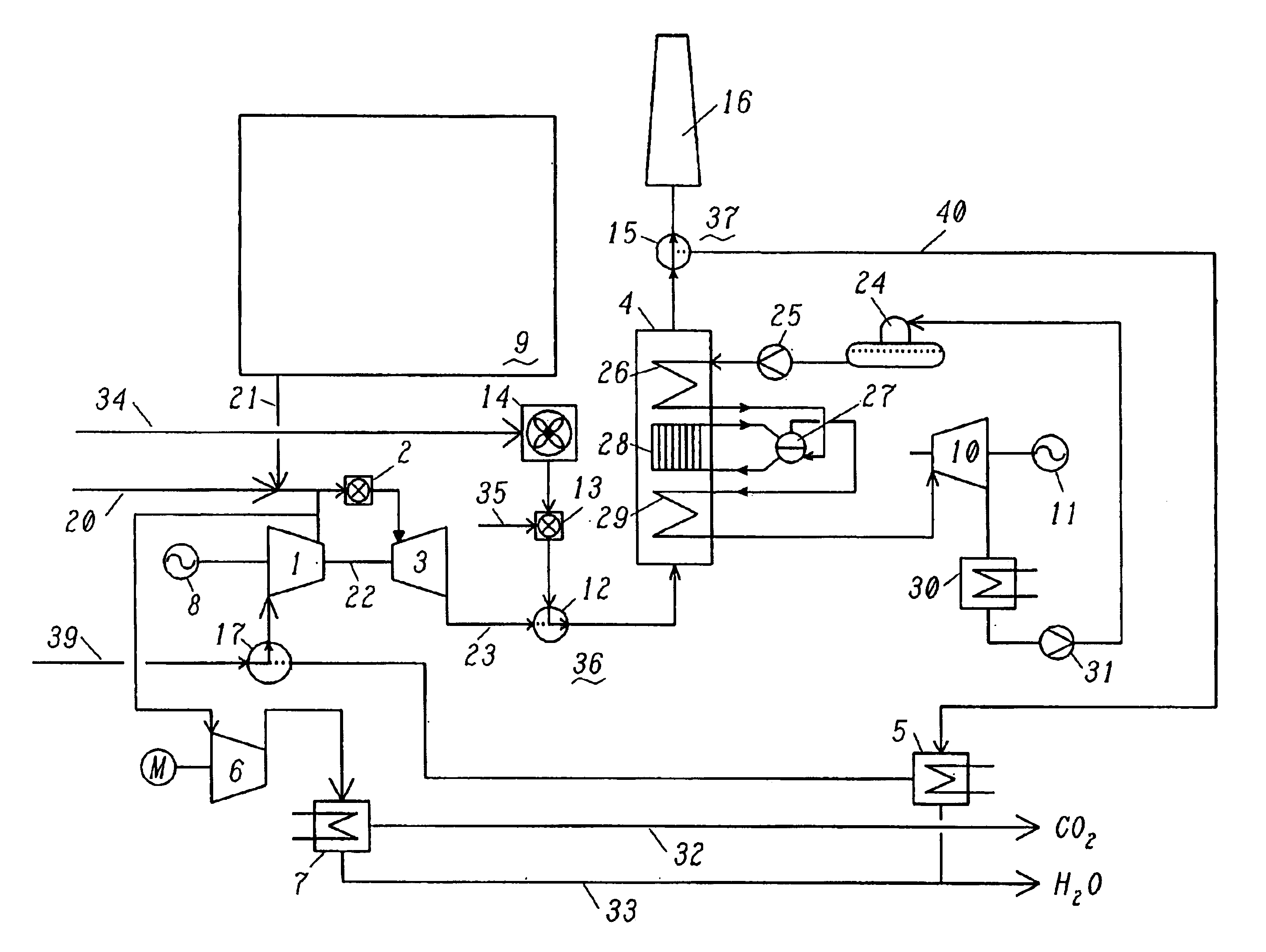
[0008]One object of the invention is therefore to provide an emission-free, semi-closed power station plant of the abovementioned type, that is to say according to the preamble of patent claim 1, which power station plant operation and start-up with minimum start-up output.

[0009]The present invention achieves this object by first means being arranged which alternatively or additionally allow hot gas to be fed into the hot-gas path between gas turbine and heat-recovery boiler, and by second means being arranged which alternatively or additionally allow exhaust gas to be expelled from the exhaust-gas path downstream of the heat-recovery boiler.

[0010]This surprisingly simple modification of the gas turbine cycle allows the heating of the heat-recovery boiler while the turboset is stopped or still does not have sufficiently high capacity (or even no longer has sufficiently high capacity), in such a way that the steam turbine cycle can be operated in an energy-generating or in particular...


PUM


Abstract

In a power generation plant having at least one gas turbine cycle with heat-recovery boiler (4) and at least one steam turbine cycle operated via the heat-recovery boiler (4), the gas turbine cycle being designed to be semi-closed and essentially free of emissions and essentially comprising a compressor (1), a combustion chamber (2) arranged downstream of the compressor (1), a gas turbine (3) arranged downstream of the combustion chamber (2), a heat-recovery boiler (4) arranged downstream of the gas turbine (3), and at least one generator (8) coupled to the gas turbine (3), modes of operation with the gas turbine cycle stopped and start-up using fresh air are made possible by first means (12) being arranged which alternatively or additionally allow hot gas to be fed into the hot-gas path (23) between gas turbine (3) and heat-recovery boiler (4), and by second means (15) being arranged which alternatively or additionally allow exhaust gas to be expelled from the exhaust-gas path (40) downstream of the heat-recovery boiler (4).

Description

[0001]This application is a continuation of and claims priority under 35 U.S.C. §120 to International application no. PCT / IB02 / 04006, filed 30 Sep. 2002, and claims priority under 35 U.S.C. §119 to Swiss application no. 2001 1809 / 01, filed 1 Oct. 2001, the entireties of both of which are incorporated by reference herein.TECHNICAL FIELD[0002]The present invention relates to a power generation plant having at least one gas turbine cycle with heat-recovery boiler and at least one steam turbine cycle operated via the heat-recovery boiler, the gas turbine cycle being designed to be semi-closed and essentially free of emissions and essentially comprising a compressor, a combustion chamber arranged downstream of the compressor, a gas turbine arranged downstream of the combustion chamber, a heat-recovery boiler arranged downstream of the gas turbine, and at least one generator coupled to the gas turbine. The invention also relates to methods of starting up and of operating such a power gene...

Claims


Application Information

Patent Timeline
Patent Type & Authority Patents(United States)
IPC IPC(8): F01K21/00F01K23/10F01K21/04
CPCF01K21/047F01K23/10Y02E20/34
Inventor FRUTSCHI, HANS ULRICHGRIFFIN, TIMOTHYHOLMBERG, DANIELSPAN, ROLAND
Owner ANSALDO ENERGIA IP UK LTD
Why Eureka
Try Eureka