Immersive display with minimized image artifacts

a technology of image artifacts and display devices, applied in the field of display devices, can solve the problems of reducing the virtual experience of the viewer, affecting the visual flow, and affecting the effect of the viewer, so as to reduce the discontinuity, reduce the discontinuity, and reduce the discontinuity

Inactive Publication Date: 2014-05-08
CORNING INC
View PDF2 Cites 18 Cited by
  • Summary
  • Abstract
  • Description
  • Claims
  • Application Information

AI Technical Summary

Benefits of technology

[0009]With reference to FIG. 2, one approach to reducing discontinuities introduced into the aggregate screen by display bezels is to provide a system 100 having a sheet of transparent material 14 between the linear array of flat panel displays 10 and the viewer 16. Through the application of light deflecting elements (not shown) on one or the other of the major surfaces of the sheet of transparent material 14 near the bezels 12, coupled with ensuring some distance between such elements and the flat panel displays 10, the bezel-induced discontinuities may be reduced. The success of such an approach, however, is highly dependent on the geometries of the system 100, particularly the position and viewing angle of the viewer 16. Indeed, the geometries of the system 100 may result in a significant reduction in the discontinuities at or near location A of the agg

Problems solved by technology

While this approach yields some improvement in the virtual reality experienced by the viewer, there is one rather glaring disadvantage; namely, that the adjacent peripheral edges of the displays that comprise the bezel 12 introduce discontinuities into the aggregate screen, interrupt the visual flow, and reduce the viewer's virtual experience.
Although users may cope with the discontinuities by focusing on the image content to the best of their ability, the visible bezels 12 nevertheless remain a significant and undesirable part of the experience.
While bezel discontinuities may be reduced and/or eliminated in projection systems, such systems require a rather

Method used


Image

  • Immersive display with minimized image artifacts
  • Immersive display with minimized image artifacts
  • Immersive display with minimized image artifacts

Examples


Embodiment Construction

[0035]Reference will now be made in detail to the present preferred embodiments of the invention, examples of which are illustrated in the accompanying drawings. Whenever possible, the same reference numerals will be used throughout the drawings to refer to the same or like parts.

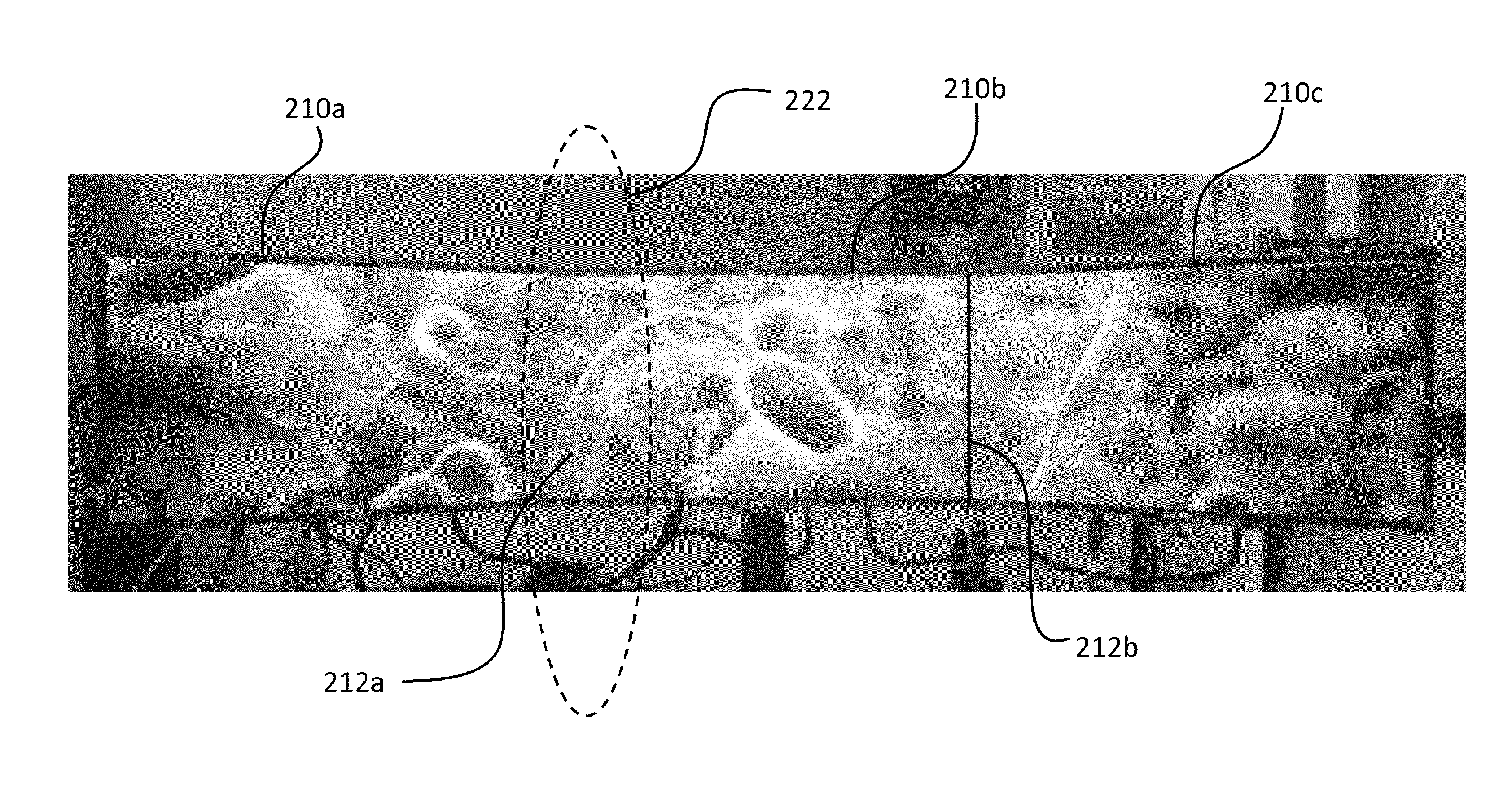
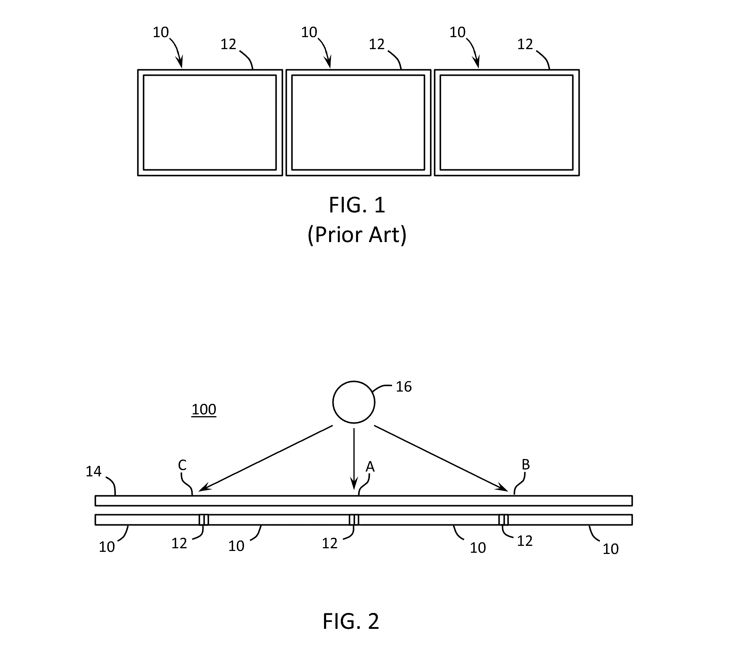
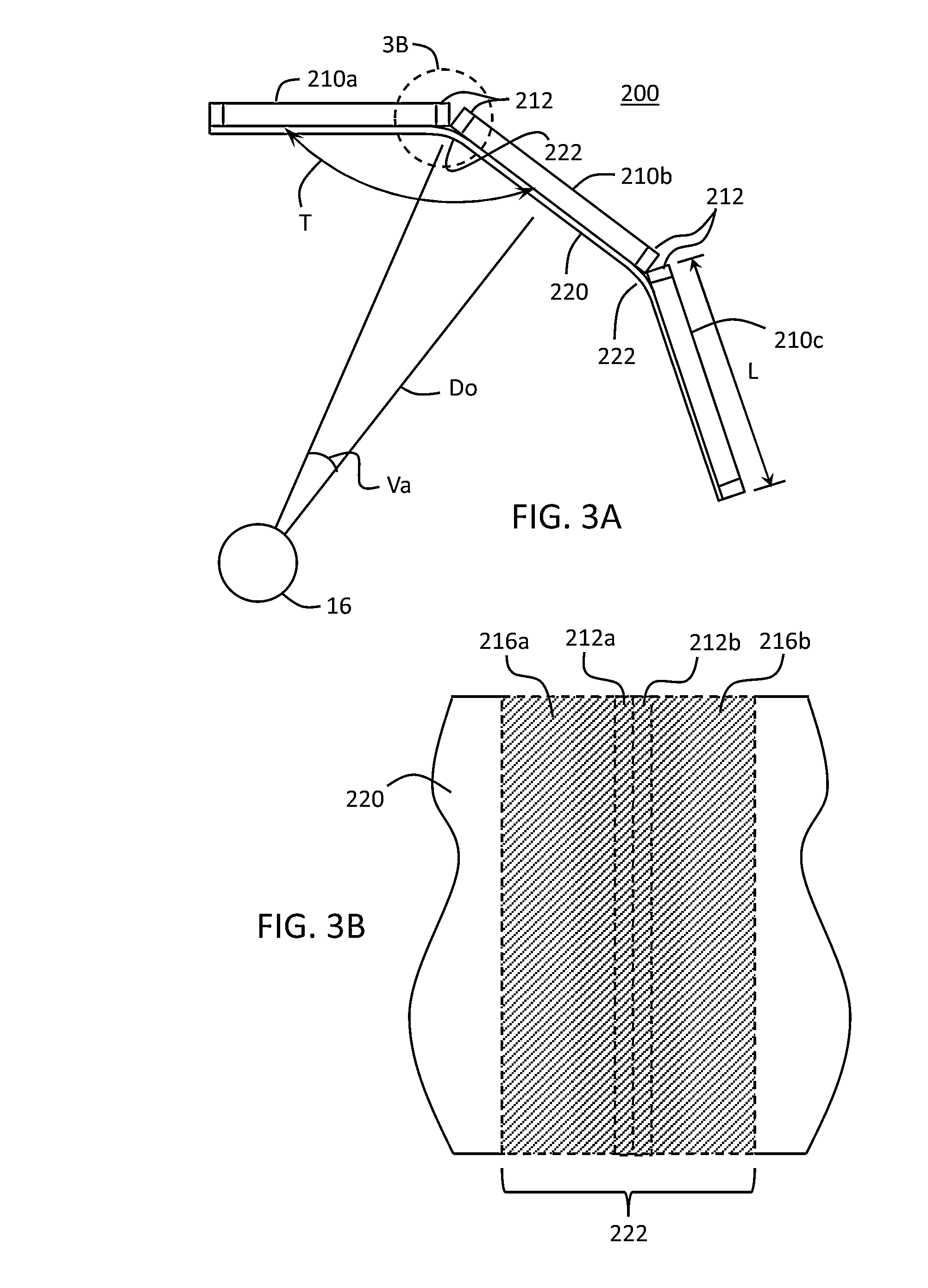
[0036]With reference to the drawings there is shown in FIG. 3A a top view (looking down on) of a display system 200 providing an enhanced viewing experience for a viewer by tiling flat panel displays in a generally curved array and providing light compensation to correct for bezel-induced discontinuities. FIG. 3B is a side, elevational view of a portion (labeled 3B) of the system of FIG. 3A.

[0037]The display system 200 includes a plurality of flat panel displays 210 (e.g. 210a, 210b and 210c) arranged in a generally curved array, and a cover sheet 220 located in proximity to, and covering the flat panel displays 210. As will be discussed in more detail below, the cover sheet 220 includes a light compensatio...


PUM


Abstract

Methods and apparatus provide for a display device comprising a plurality of display panels arranged adjacent to one another along the respective peripheral edges thereof, and wherein respective first and second viewing planes form an obtuse angle T relative to each other. The display device further includes a cover sheet located in proximity to, and covering the first and second viewing planes, and includes a light compensation portion located proximate to the peripheral edges of the first and second flat panel displays, and has a curvature complementary to the obtuse angle between the respective first and second viewing planes. The light compensation portion bends light produced by respective peripheral areas of the first and second flat panel displays proximate to the respective peripheral edges thereof to reduce visual discontinuities introduced by the peripheral edges into an image displayed on the first and second flat panel displays.

Description

CROSS-REFERENCE TO RELATED APPLICATIONS[0001]This application claims the benefit of priority under 35 U.S.C. §119(e) of U.S. Provisional Application Ser. No. 61 / 721,785 filed on Nov. 2, 2012 and U.S. Provisional Application Ser. No. 61 / 783,495 filed on Mar. 14, 2013, the contents of which are incorporated herein by reference in their entirety.BACKGROUND[0002]1. Field[0003]The present invention relates generally to display devices, and particularly to immersive display devices comprising a plurality of adjacent flat panel displays and an arcuate cover sheet positioned proximate the flat panel display.[0004]2. Technical Background[0005]As digital imaging technology rapidly advances, viewers of images on digital displays demand higher and higher image quality and a contemporaneous increase in the level of virtual reality that they experience through the display. Indeed, viewers wish to attain the feeling that they are actually in a virtual 3D space at least in part through the way the ...

Claims


Application Information

Patent Timeline
IPC IPC(8): F21V5/02
CPCF21V5/02G02B5/045G02B27/1066G02F1/13336G02F1/1335G02F1/133509G02F1/133524G02F1/133605G02F2203/62G06F1/1609G06F1/1641G02F1/133388G02F1/133562G02F1/133607H04R7/045H04R7/06H04R2499/15H04R1/028H04R7/12
Inventor GENG, YINGGOLLIER, JACQUES
Owner CORNING INC
Why Eureka
Try Eureka