Hydroformed driveshaft tube with secondary shape

a drive shaft and secondary shape technology, applied in the direction of springs/dampers, mechanical equipment, vibration suppression adjustments, etc., can solve the problems of excessive wear of a plurality of driveshaft components, unsatisfactory vibration of the driveshaft, and customer dissatisfaction, so as to reduce the cost of the driveshaft and increase the critical speed

Inactive Publication Date: 2014-05-08
DANA AUTOMOTIVE SYST GRP LLC
View PDF6 Cites 11 Cited by
  • Summary
  • Abstract
  • Description
  • Claims
  • Application Information

AI Technical Summary

Benefits of technology

[0009]Presently provided by the invention, a driveshaft that may be formed using a hydroforming process, reduces a cost of the driveshaft, and has an increased critical speed, has surprisingly been discovered.

Problems solved by technology

Rotation of a driveshaft at or near a resonating frequency of the driveshaft may lead to an undesired vibration of the driveshaft.
Further, rotation of a driveshaft which is unbalanced may also lead to the undesired vibration of the driveshaft, resulting in customer dissatisfaction.
Rotation of the driveshaft with the undesired vibration, regardless of its source, may also lead to excessive wear of a plurality of components of the driveshaft.
Center bearings, shaft end components (such as yokes), universal joint crosses, needle bearings, and a tubular portion of the driveshaft may all be excessively worn by the undesired vibration of the driveshaft.
Unfortunately, adding joints to the driveshaft greatly increases a cost and a weight of the driveshaft, and thus a vehicle the driveshaft is incorporated in.
However, increasing the diameter of the driveshaft and the diameter of the shaft end components also greatly increases the cost of the driveshaft, and thus the vehicle the driveshaft is incorporated in.
However, balancing of the driveshaft increases a time of manufacture of the driveshaft and therefore increases the cost of the driveshaft, and thus the vehicle the driveshaft is incorporated in.
However, conventional methods used to hydroform driveshafts as applied to aluminum have been unsuccessful, as a maximum strain limit for forming aluminum is less than a maximum strain limit for forming steel.

Method used


Image

  • Hydroformed driveshaft tube with secondary shape
  • Hydroformed driveshaft tube with secondary shape
  • Hydroformed driveshaft tube with secondary shape

Examples


Embodiment Construction

[0024]It is to be understood that the invention may assume various alternative orientations and step sequences, except where expressly specified to the contrary. It is also to be understood that the specific devices and processes illustrated in the attached drawings, and described in the following specification are simply exemplary embodiments of the inventive concepts defined in the appended claims. Hence, specific dimensions, directions or other physical characteristics relating to the embodiments disclosed are not to be considered as limiting, unless the claims expressly state otherwise.

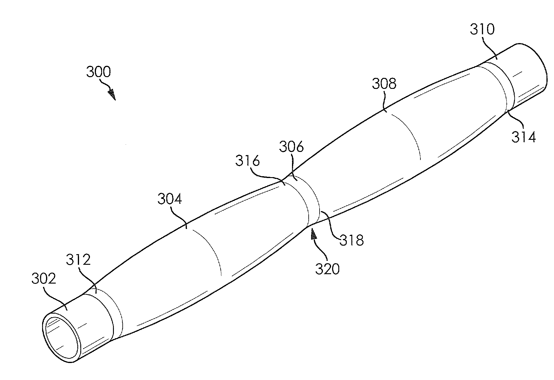
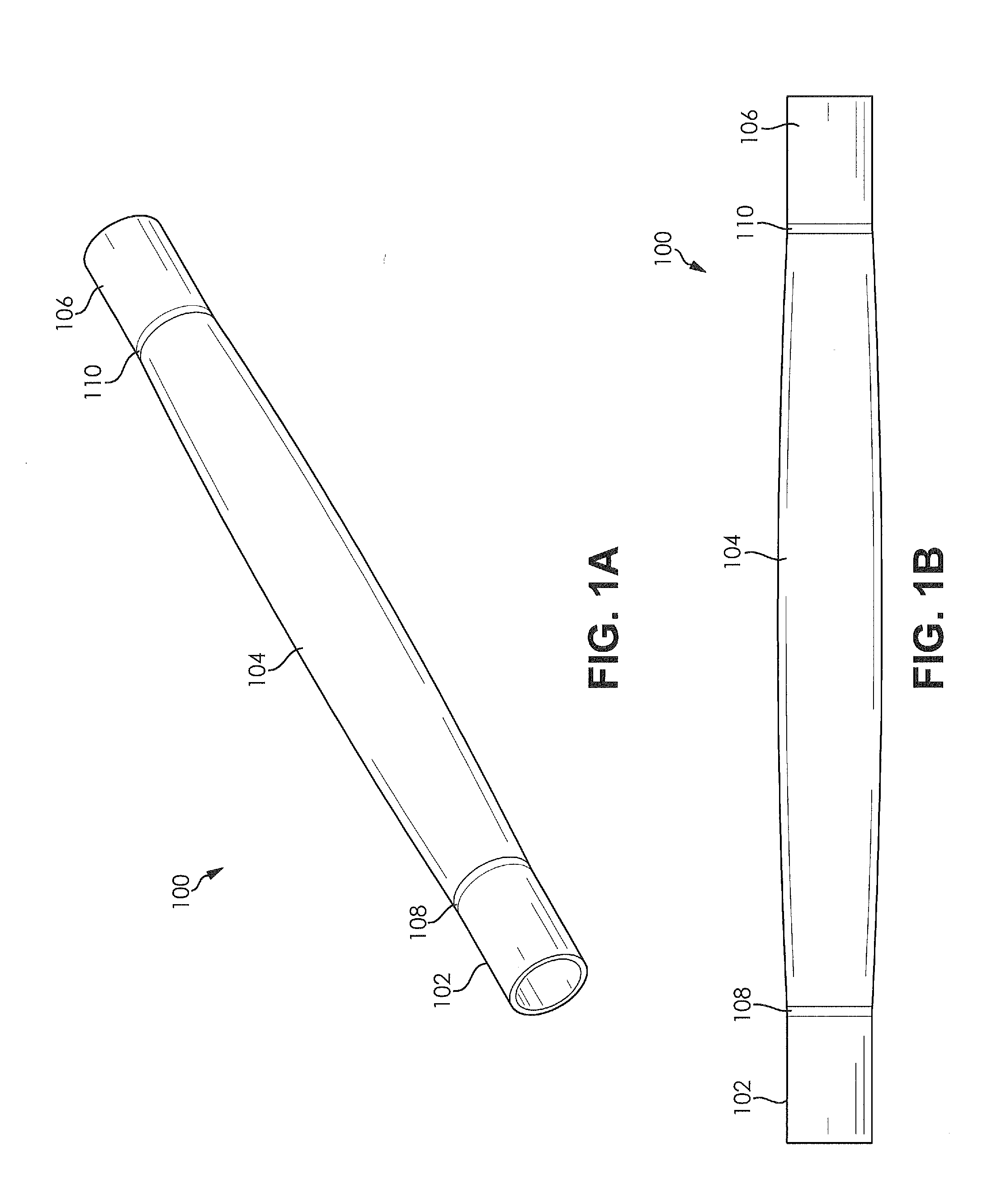
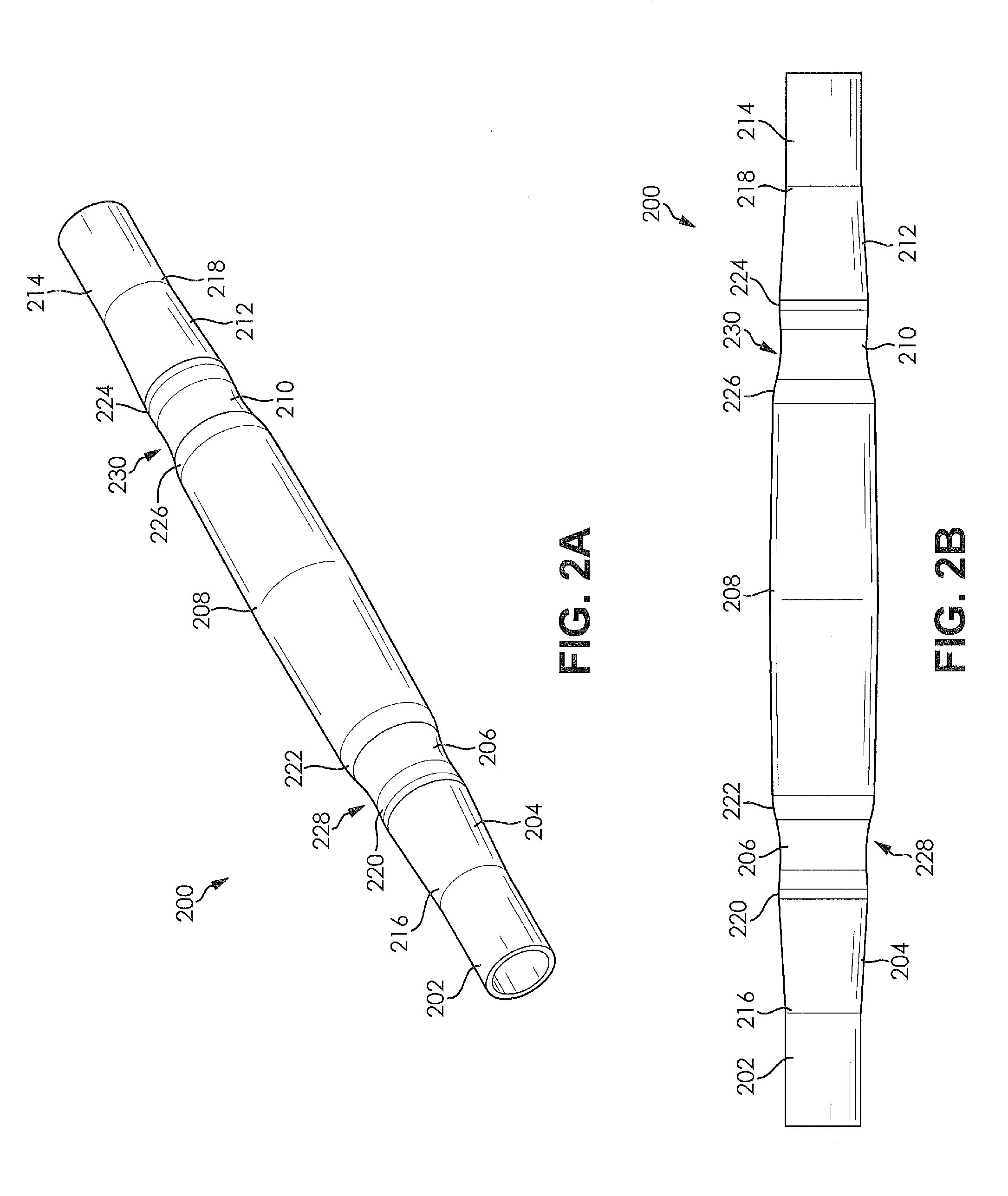
[0025]FIGS. 1A and 1B illustrate a first driveshaft tube 100 formed using a hydroforming process. The first driveshaft tube 100 is formed from a 6061 aluminum alloy; however, it is understood that other alloys may be used. A tubular aluminum blank (not illustrated) used to form the first driveshaft tube 100 using the hydroforming process may be formed using an extrusion process or a seam welding p...


PUM

PropertyMeasurementUnit
acute angleaaaaaaaaaa

Abstract

A hydroformed driveshaft tube formed using a hydroforming process is provided. The hydroformed driveshaft tube comprises a first end portion, a second end portion, and a middle portion. The middle portion is at least partially defined by a circular arc shaped surface of revolution. At least a portion of the middle portion has a diameter greater than a diameter of the first end portion and the second end portion. The middle portion is formed between the first end portion and the second end portion. The middle portion affects a critical speed and a breathing mode frequency of the hydroformed driveshaft tube. The hydroformed driveshaft tube reduces a cost of a driveshaft assembly.

Description

CLAIM OF PRIORITY[0001]The present application claims the benefit of priority to U.S. Provisional Application No. 61 / 724,154 filed on Nov. 8, 2012, which is incorporated herein in its entirety by reference.FIELD OF THE INVENTION[0002]The present invention relates to driveshafts and more specifically to driveshafts for vehicle formed using a hydroforming process.BACKGROUND OF THE INVENTION[0003]Rotation of a driveshaft at or near a resonating frequency of the driveshaft may lead to an undesired vibration of the driveshaft. Further, rotation of a driveshaft which is unbalanced may also lead to the undesired vibration of the driveshaft, resulting in customer dissatisfaction. Rotation of the driveshaft with the undesired vibration, regardless of its source, may also lead to excessive wear of a plurality of components of the driveshaft. Center bearings, shaft end components (such as yokes), universal joint crosses, needle bearings, and a tubular portion of the driveshaft may all be exces...

Claims


Application Information

Patent Timeline
Patent Type & Authority Applications(United States)
IPC IPC(8): F16C3/02
CPCF16C3/02B21D26/033B21D53/84F16F15/10F16F15/322
Inventor LASKEY, RYAN W.DUTKIEWICZ, JEFFREY A.
Owner DANA AUTOMOTIVE SYST GRP LLC
Why Eureka
Try Eureka