Adaptive energy management system

Inactive Publication Date: 2014-05-08
EMADI ALI +2
View PDF24 Cites 104 Cited by
  • Summary
  • Abstract
  • Description
  • Claims
  • Application Information

AI Technical Summary

Benefits of technology

[0006]The present invention provides systems, methods, and devices related to a microgrid system for providing power to a facility. A self-contained power system provides power to a facility using a combination of power storage elements and renewable energy sources. A connection to an external power grid may also be provided. The system optimizes power flow to the facility using power from the storage elements and the renewable energy sources and, if necessary, the external power grid. The optim

Problems solved by technology

However, currently there are no systems which integrate the different available environmentally friendly energy and power technolo

Method used


Image

  • Adaptive energy management system
  • Adaptive energy management system
  • Adaptive energy management system

Examples


Embodiment Construction

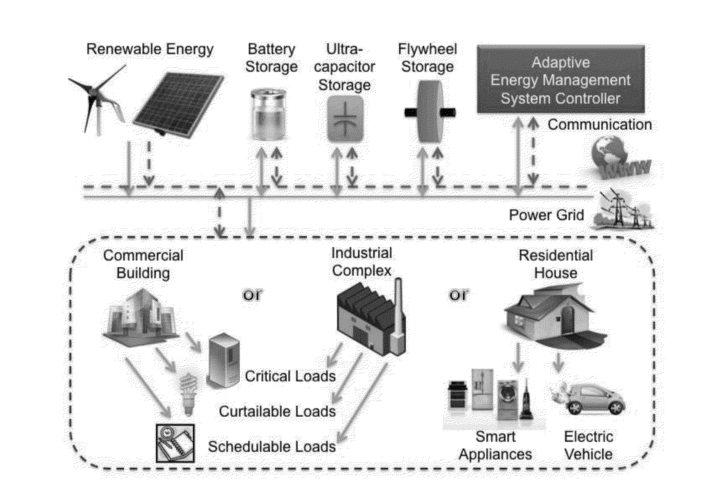
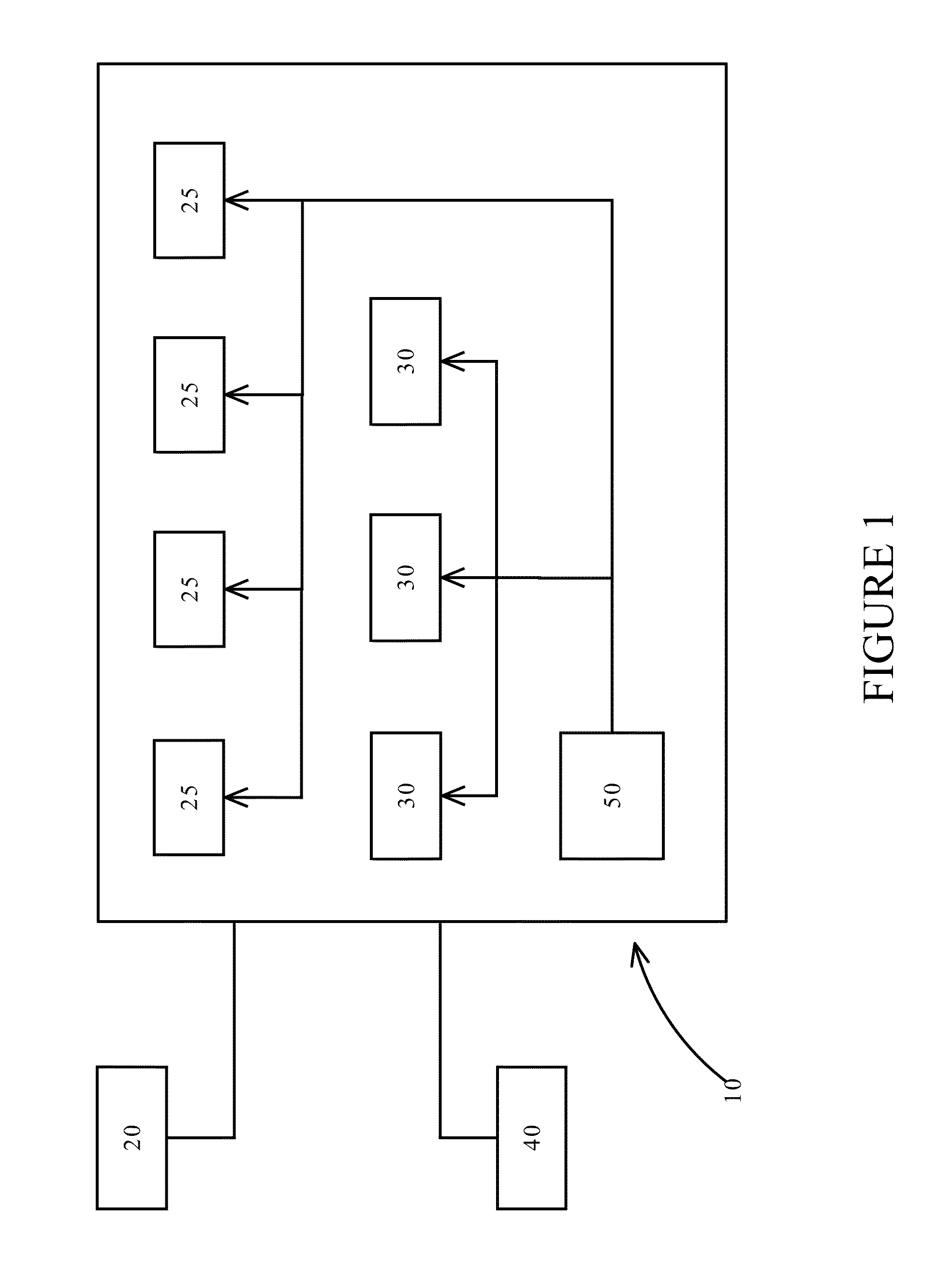
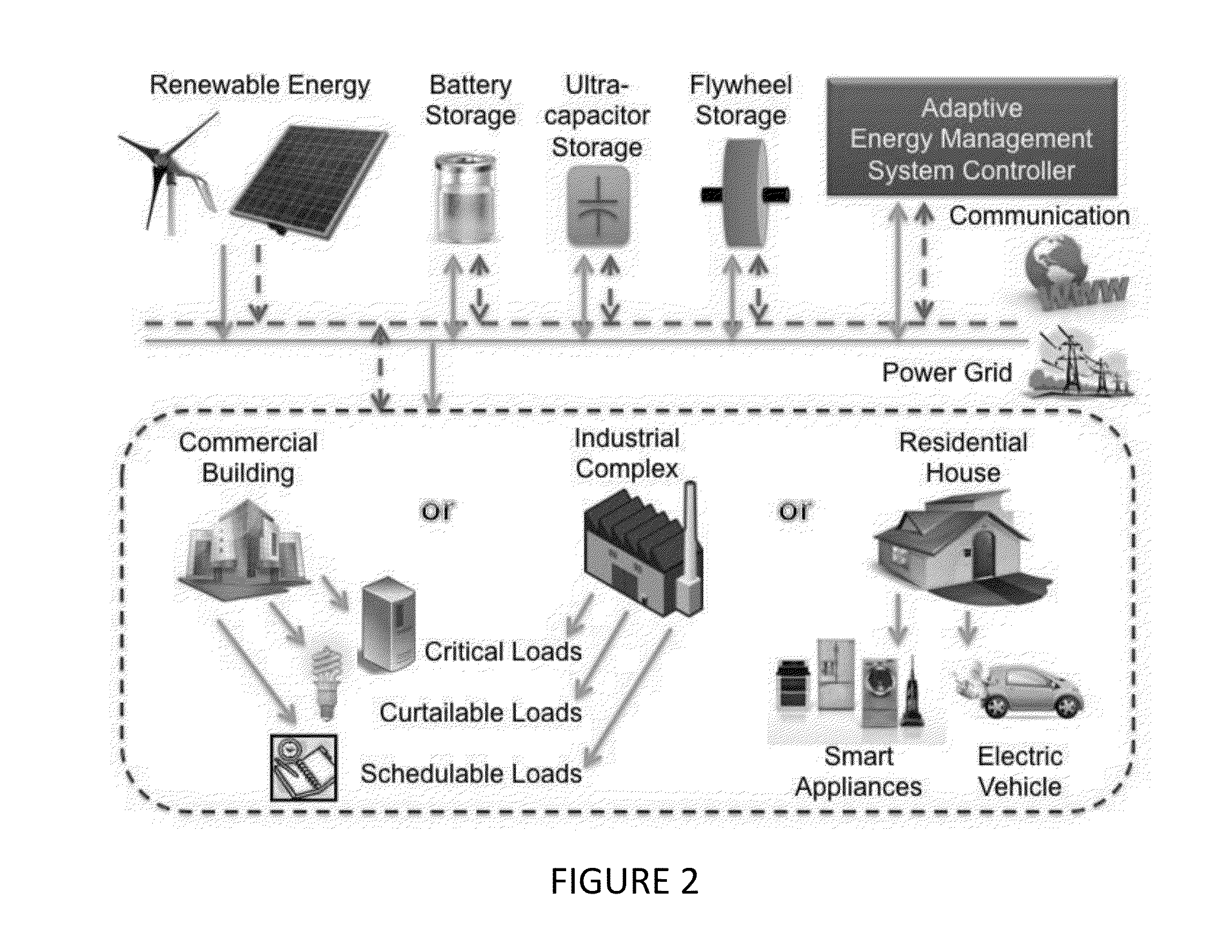
[0042]Referring to FIG. 1, a block diagram of one aspect of the invention is illustrated. A power system 10 supplies and manages a power flow to a facility 20. As part of the system 10, renewable energy sources 25 generate power when required. Energy storage elements 30 are also part of the system 10. The energy storage elements 30 store power from different sources so that it may be used when needed by the system. An external power grid 40 can also be coupled to the system 10. As will be described below, the external power grid can be disconnected but this grid can be called upon to provide power if necessary. A controller 50 controls the power flow within the system 10 and determines where power is to be taken from and where it is to be routed. As will be described below, an optimization process is executed on the controller 50 and this process determines the various power flows within the system 10. In one embodiment, the controller 50 not only controls the various energy sources...


PUM


Abstract

Systems, methods, and devices related to a microgrid system for providing power to a facility. A self-contained power system provides power to a facility using a combination of power storage elements and renewable energy sources. A connection to an external power grid may also be provided. The system optimizes power flow to the facility using power from the storage elements and the renewable energy sources and, if necessary, the external power grid. The optimization process predicts future power usage by the facility using power usage data from a predetermined time window. The optimization process can also take into account predicted energy generation amounts by the renewable energy sources. To optimize economic effects, the optimization process can also determine whether to buy and when to buy power from the external power grid.

Description

TECHNICAL FIELD[0001]The present invention relates to energy management. More specifically, the present invention relates to systems, methods, and devices for providing an optimized power flow to and from a facility whose power needs are met by a collection of renewable energy sources, energy storage elements, and a potential link to an external power grid.BACKGROUND OF THE INVENTION[0002]The potential energy crisis due to disappearing fossil fuel sources and the pollution caused by these traditional fossil fuels is well-known. Awareness of this issue and a growing willingness among the populace to work towards alleviating the effects of the looming shortage of fossil fuels and its pollution has given rise to the increasing use of so-called “green” or environmentally friendly technologies, including technologies that relate to renewable energy sources.[0003]This growing trend of using consumer-accessible green energy technology, such as solar / wind power, electrified vehicles, and on...

Claims


Application Information

Patent Timeline
IPC IPC(8): G06Q50/06
CPCG06Q50/06Y02E40/70Y04S10/50
Inventor EMADI, ALISIROUSPOUR, SHAHINMALYSZ, PAWEL
Owner EMADI ALI
Why Eureka
Try Eureka