Air filtering device in an air intake line of an internal combustion engine
a filtering device and air intake technology, which is applied in the direction of air cleaner and silencer combination, auxillary pretreatment, separation processes, etc., can solve the problems of clogging of said central region, short service life of the filter cartridge, and the risk of not being suitable for a small engine compartment, so as to dampen low frequency vibration and dampen air vibration
- Summary
- Abstract
- Description
- Claims
- Application Information
AI Technical Summary
Benefits of technology
Problems solved by technology
Method used
Image
Examples
second embodiment
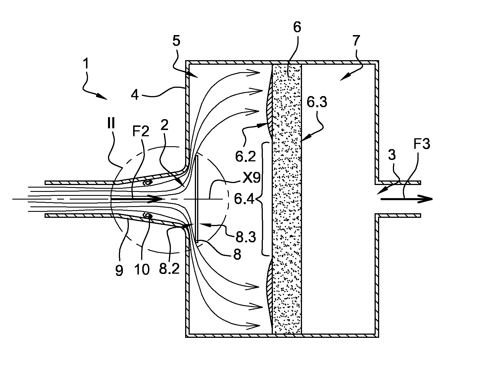
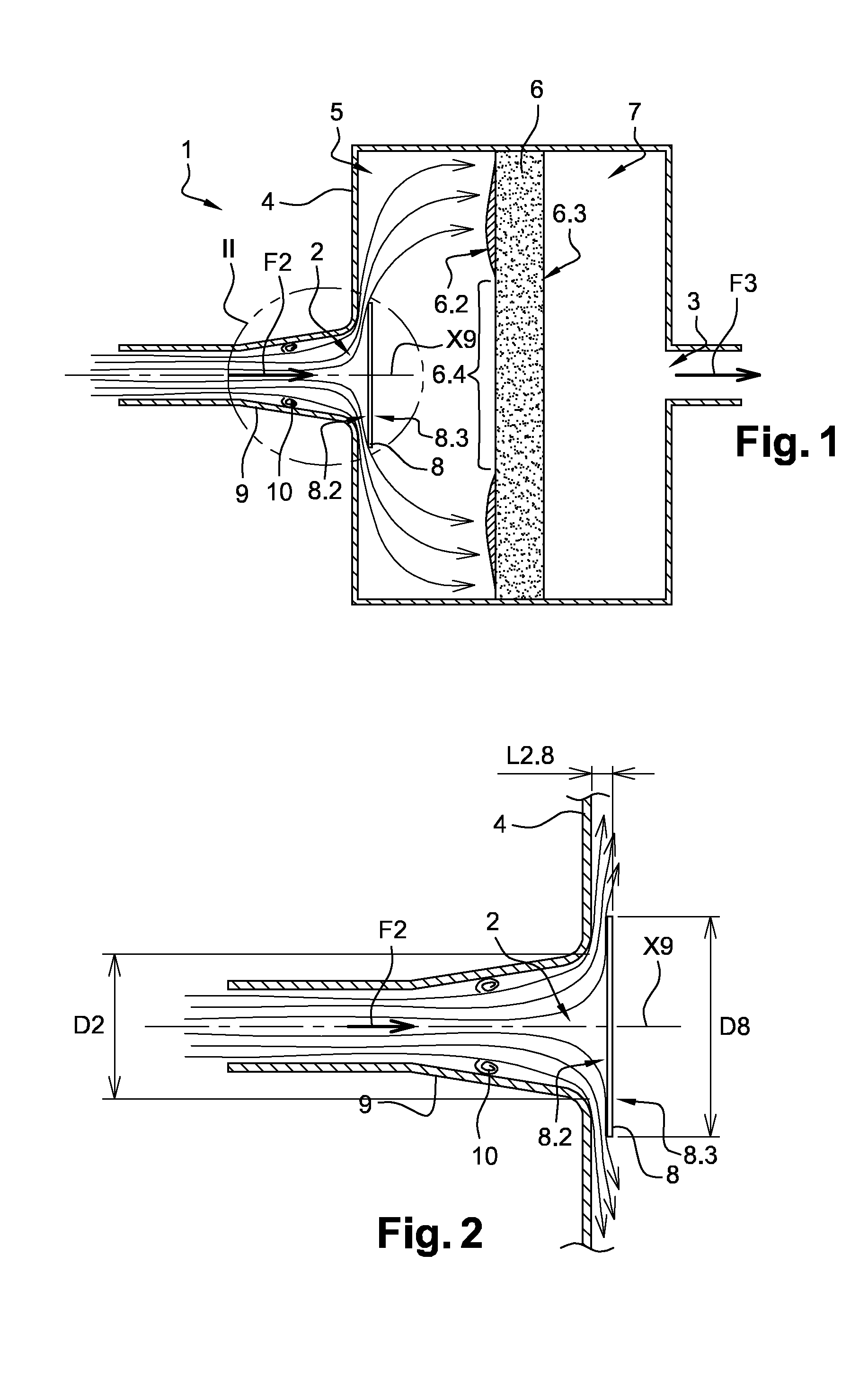
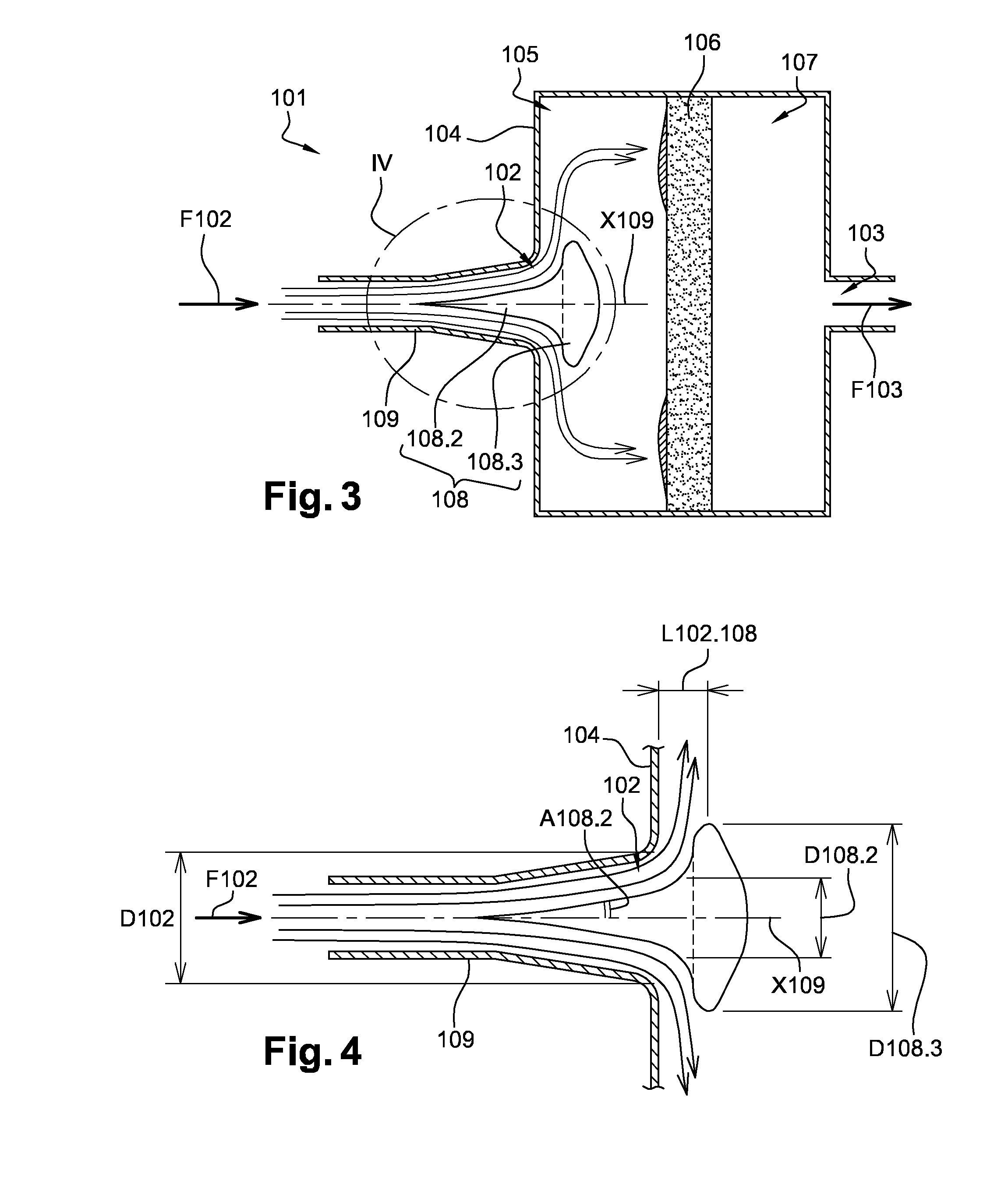
[0091]FIGS. 3 and 4 illustrate a filtering device 101 according to the invention. Insofar as the filtering device 101 is similar to the filtering device 1, the description of the filtering device 1 provided above in relation to FIGS. 1 and 2 may be transferred to the filtering device 101, with the exception of the notable differences mentioned below.
[0092]A component of the filtering device 101 which is identical or corresponds by its structure or by its function to a component of the filtering device 1 bears the same reference numeral increased by 100. One can thus define an inlet orifice 102, a flow of dirty air F102, an outlet orifice 103, a flow of filtered air F103, a housing 104 with an inlet compartment 105 and a filtering element 106, an outlet compartment 107, a deflector 108 and an inlet conduit 109 with an axis of symmetry X109.
[0093]The filtering device 101 differs from the filtering device 1, in particular, in that the deflector 108 has approximately the shape of a nail...
third embodiment
[0101]FIG. 5 illustrates a part of a filtering device 201 according to the invention. Insofar as the filtering device 201 is similar to the filtering device 1, the description of the filtering device 1 provided above in relation to FIGS. 1 and 2 may be transferred to the filtering device 201, with the exception of the notable differences mentioned below.
[0102]A component of the filtering device 201 which is identical or corresponds by its structure or by its function to a component of the filtering device 1 bears the same reference numeral increased by 200. One can thus define an inlet orifice 202, a flow of dirty air F202, a flow of filtered air F203, a housing 204 with an inlet compartment 205 and a filtering element 206, a deflector 208 and an inlet conduit 209 with an axis of symmetry X209.
[0103]The filtering device 201 differs from the filtering device 1, in particular, in that the deflector 208 has a lateral surface 208.5 which is cylindrical and which extends between the upst...
fourth embodiment
[0119]FIG. 7 illustrates part of a filtering device 401 according to the invention. Insofar as the filtering device 401 is similar to the filtering device 201, the description of the filtering device 201 provided above in relation to FIG. 5 may be transferred to the filtering device 401, with the exception of the notable differences mentioned below.
[0120]A component of the filtering device 401 which is identical or corresponds by its structure or by its function to a component of the filtering device 201 bears the same reference numeral increased by 200. One can thus define an inlet orifice 402, a flow of dirty air F402, a flow of filtered air F403, a housing 404 with an inlet compartment 405 and a filtering element 406, a deflector 408 with an upstream surface 408.2, a downstream surface 408.3 and a cavity 408.6, an inlet conduit 409 with an axis of symmetry X409, collection holes 411 and 412, a discharge conduit 413 and a low-pressure bringing hole pressure 414.
[0121]The filtering...
PUM
| Property | Measurement | Unit |
|---|---|---|
| Frequency | aaaaa | aaaaa |
| Frequency | aaaaa | aaaaa |
| Thickness | aaaaa | aaaaa |
Abstract
Description
Claims
Application Information
 - R&D
- Intellectual Property
- Life Sciences
- Materials
- Tech Scout
- Unparalleled Data Quality
- Higher Quality Content
- 60% Fewer Hallucinations
Browse by: Latest US Patents, China's latest patents, Technical Efficacy Thesaurus, Application Domain, Technology Topic, Popular Technical Reports.
© 2025 PatSnap. All rights reserved.Legal|Privacy policy|Modern Slavery Act Transparency Statement|Sitemap|About US| Contact US: help@patsnap.com


