Concealable Toilet Paper Spindle and Method of Use

Active Publication Date: 2014-05-15
CLARKIN CHAD
View PDF6 Cites 27 Cited by
  • Summary
  • Abstract
  • Description
  • Claims
  • Application Information

AI Technical Summary

Benefits of technology

[0007]Toilet paper holders that conceal the toilet paper when not in use have been devised in the past. General problems with these toilet paper holders is that they either are a part of a cabinet storage syst

Problems solved by technology

General problems with these toilet paper holders is that they either are a part of a cabinet storage system, which takes up a lot of space in the bathroom, o

Method used


Image

  • Concealable Toilet Paper Spindle and Method of Use
  • Concealable Toilet Paper Spindle and Method of Use
  • Concealable Toilet Paper Spindle and Method of Use

Examples


Embodiment Construction

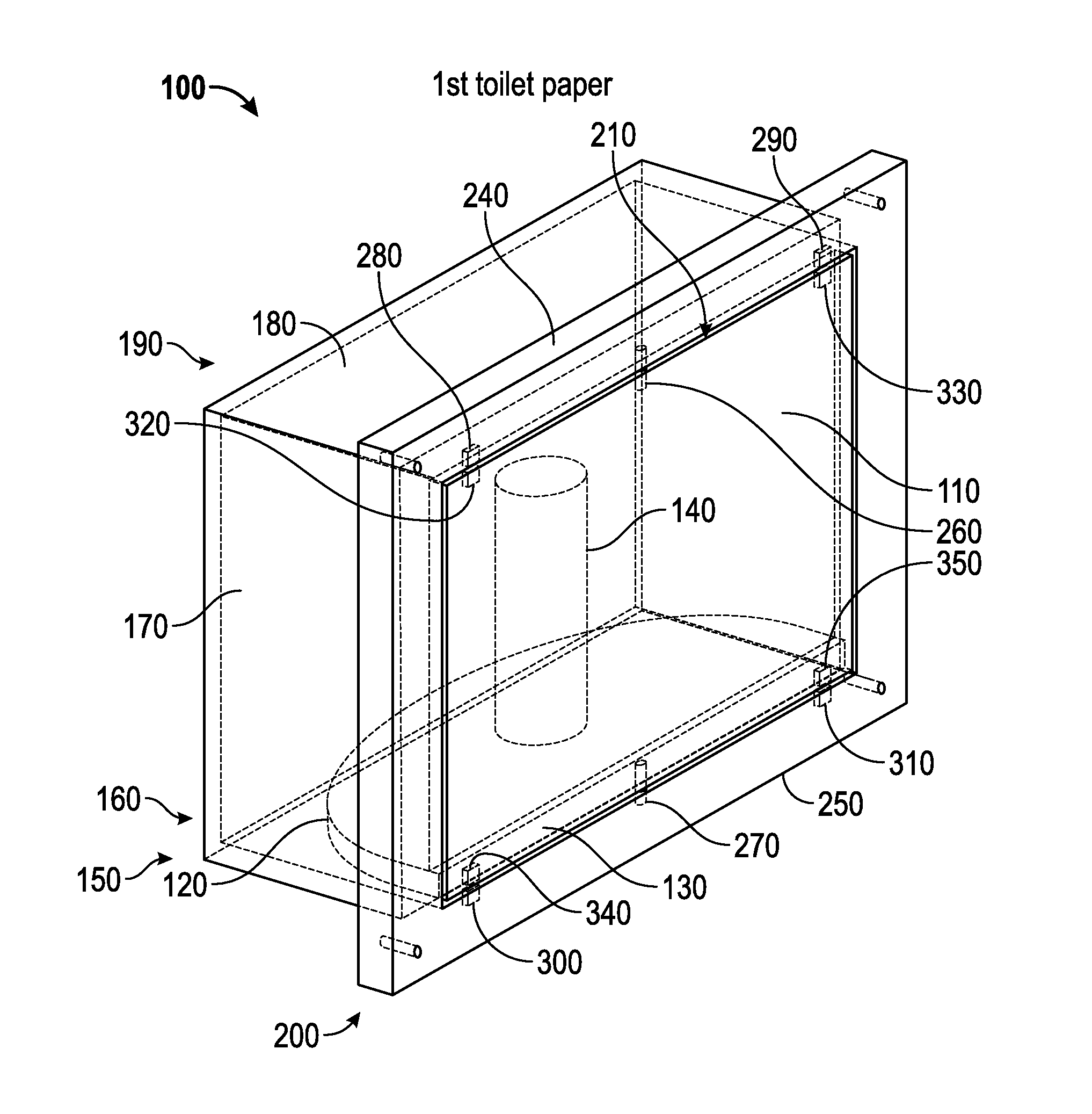
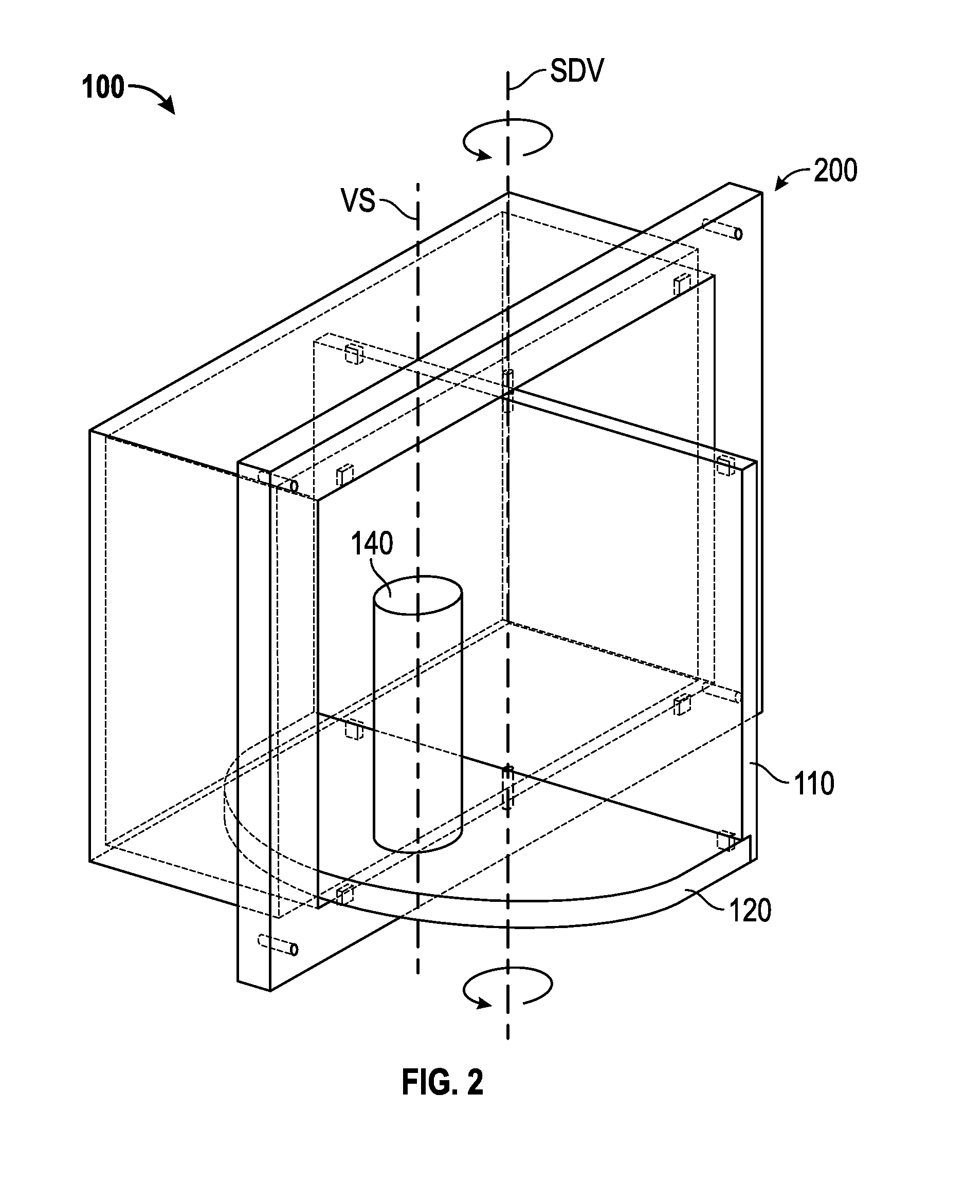
[0025]With reference initially to FIGS. 1-8, an embodiment of a concealable toilet paper spindle 100 will be described. FIGS. 1 and 4-8 show the concealable toilet paper spindle 100 in a closed condition where toilet paper on and in the spindle 100 is concealed. FIG. 2 shows the spindle 100 in a partially open condition. FIG. 3 shows the spindle 100 in a completely open condition.

[0026]The spindle 100 includes a thin rectangular front door panel or door 110 and a half circle platform 120 extending laterally along a bottom edge 130 of the door panel 100. A vertical spindle 140 extends upwardly from a substantial center of the platform 120. The vertical spindle 140 includes a central longitudinal axis VS 80 (See FIG. 2). In the closed condition shown in FIG. 1, the door panel 100, platform 120, and vertical spindle 140 are disposed with a framed housing 150. The framed housing 150 has a substantially rectangular box shaped housing member 160 with parallel side walls 170, parallel top / ...


PUM


Abstract

A concealable waste paper holder for dispensing waste paper from a waste paper roll includes a frame mountable to a wall; a door rotatably mounted to the frame about a door rotational axis between an open position where the waste paper roll is accessible and a closed position where the door is substantially parallel with the wall and conceals the waste paper roll; a spindle for rotationally receiving the waste paper roll about a spindle axis and dispensing the waste paper from the waste paper roll there when the door is is the open position, the spindle carried by the door for rotation with the door, and wherein the spindle axis and the door rotational axis are parallel.

Description

CROSS-REFERENCE TO RELATED APPLICATION[0001]The present application claims priority to U.S. provisional patent application 61 / 825,353 filed May 20, 2013 and U.S. provisional patent application 61 / 725,568 filed Nov. 13, 2012 under 35 U.S.C. 119. Both of these applications are incorporated by reference herein.FIELD OF THE INVENTION[0002]This invention relates generally to toilet paper holders for the bathroom and particularly to toilet paper holders that conceal the toilet paper when not in use.SUMMARY OF THE INVENTION[0003]An aspect of the invention involves a concealable waste paper holder for dispensing waste paper from a waste paper roll. The concealable waste paper holder includes a frame mountable to a wall; a door rotatably mounted to the frame about a door rotational axis between an open position where the waste paper roll is accessible and a closed position where the door is substantially parallel with the wall and conceals the waste paper roll; a spindle for rotationally rec...

Claims


Application Information

Patent Timeline
IPC IPC(8): A47K10/38
CPCA47K10/38A47K1/09A47K3/281A47K10/3836A47K17/00A47K2010/3233E04F19/08
Inventor CLARKIN, CHAD
Owner CLARKIN CHAD
Why Eureka
Try Eureka