Clean, low-pressure EGR in a turbocharged engine by back-pressure control

a turbocharged engine and low-pressure technology, applied in the field of motor vehicles, to achieve the effect of reducing or even eliminating the penalty

Active Publication Date: 2006-11-07
INT ENGINE INTPROP CO LLC
View PDF16 Cites 38 Cited by
  • Summary
  • Abstract
  • Description
  • Claims
  • Application Information

AI Technical Summary

Benefits of technology

[0011]The present invention is a consequence of the inventors' recognition that use of throttling of engine intake flow in order to accommodate LP EGR in a turbocharged engine imposes a fuel economy. Consequently, an objective of the present invention is to minimize, or even eliminate, that penalty.
[0014]While accomplishing the foregoing, the invention also provides advantages in the fabrication of certain engine system components and their packaging in a motor vehicle. For example, both an exhaust back-pressure control valve and LP EGR valve can be packaged as a single component or device that can be assembled in a motor vehicle outside the engine compartment, such as in an undercarriage of the vehicle rearward of the engine compartment. This has the potential for saving space in an engine compartment where available space is often at a premium.

Problems solved by technology

The extent to which such a system can provide increased EGR flow that is desired in order to eliminate more NOx from tailpipe emissions is limited by compressor inlet depression.

Method used


Image

  • Clean, low-pressure EGR in a turbocharged engine by back-pressure control
  • Clean, low-pressure EGR in a turbocharged engine by back-pressure control

Examples


Embodiment Construction

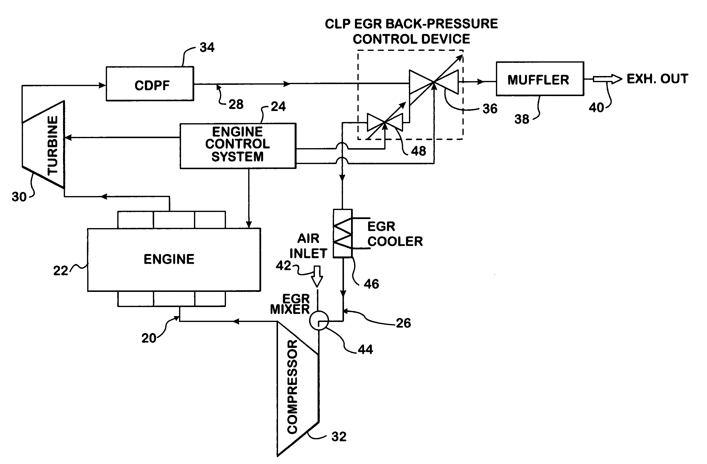
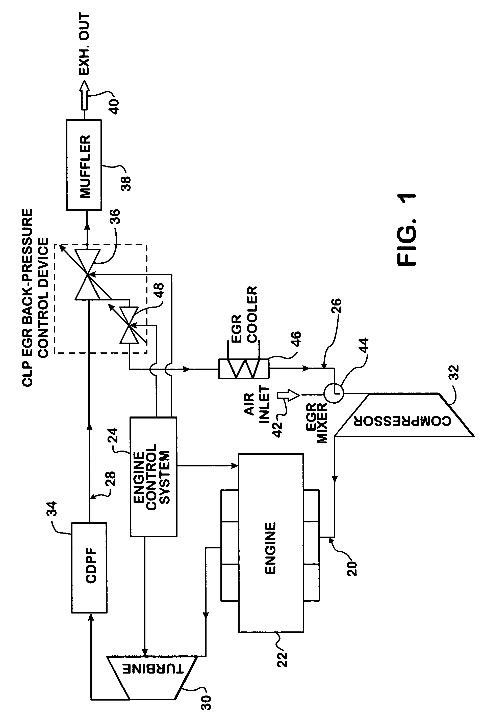
[0020]FIG. 1 shows an engine system 20 embodying principles of the invention as an example of an internal combustion engine system of a motor vehicle. Engine system 20 comprises a diesel engine 22 under the control of a processor-based engine control system 24 that processes data from various sources to develop various control data for controlling various aspects of engine operation. The data processed by control system 24 may originate at external sources, such as sensors, and / or be generated internally. A processor of control system 24 can process data sufficiently fast to enable controlled functions to respond quickly to changes.

[0021]Engine system 20 further comprises an intake system 26 through which charge air enters combustion chambers of engine 22 and an exhaust system 28 through which exhaust gases resulting from combustion leave engine 22. Engine 22 is turbocharged by a turbocharger that comprises a turbine 30 in exhaust system 28 and a compressor 32 in intake system 26.

[0...


PUM


Abstract

An engine system (20) includes an intake system (26) through which charge air enters combustion chambers, and an exhaust system (28) that includes a CDPF (34), through which products of combustion pass to the surrounding atmosphere. A throttle valve (36) is located in The exhaust system (28) downstream of both the CDPF (34) and the turbocharger turbine (30). An EGR flow path for recirculating exhaust gas from the exhaust system to the intake system includes an EGR valve (48) for controlling EGR flow. The EGR flow path is connected to the exhaust system upstream of the throttle valve and downstream of both the CDPF and the turbine, and to the intake system upstream of the turbocharger compressor Valves (36, 48) are under coordinated control provided by an engine control system (24) for selectively restricting the respective valves to attain desired EGR flow.

Description

FIELD OF THE INVENTION[0001]This invention relates to motor vehicles that are powered by internal combustion engines that use EGR (exhaust gas recirculation) as an element of their tailpipe emission control strategies. More specifically, the invention relates to systems and methods in turbocharged engines for obtaining clean, low-pressure EGR by exhaust back-pressure control.BACKGROUND OF THE INVENTION[0002]The recirculation of some engine exhaust gas is a recognized technique for achieving compliance with applicable tailpipe emission requirements. NOX emissions in particular. Various EGR strategies have been proposed for turbocharged engines, including diesel engines. Examples appear in U.S. Pat. Nos. 6,422,217; 6,263,672; 6,000,222; 5771,867; 5,671,600; and 4,215,550.[0003]U.S. Pat. No. 6,422,217 describes a device that is placed in an engine exhaust system between the engine exhaust manifold and the turbocharger turbine. The device contains a valve mechanism for controlling engin...

Claims


Application Information

Patent Timeline
Patent Type & Authority Patents(United States)
IPC IPC(8): F02B33/44F02M25/07F01N3/023F01N3/035F02B37/00
CPCF01N3/023F01N3/0235F02D9/04F02M25/0709F02M25/0713F02M25/0718F01N3/0231F01N3/035F01N2570/10F01N2570/12F02B37/00F02M25/0727Y02T10/121F02M26/06F02M26/10F02M26/15F02M26/23
Inventor BULICZ, TYTUS R.EL-BESHBEESHY, MAHMOUD S.CHEN, KAIPROCHNAU, TIMOTHY J.
Owner INT ENGINE INTPROP CO LLC
Why Eureka
Try Eureka