
Optical irradiation device having LED and heat pipe

a technology of optical irradiation and heat pipe, which is applied in the direction of instruments, printers, therapy, etc., can solve the problems of reducing the efficiency of dental treatment delivered, and achieve the effects of reducing the power required to drive the device and the heat generated by the device, increasing the irradiance, and increasing the radiant intensity

Inactive Publication Date: 2010-01-12
SIGNIFY HLDG BV +1
View PDF206 Cites 40 Cited by
  • Summary
  • Abstract
  • Description
  • Claims
  • Application Information

AI Technical Summary

Benefits of technology

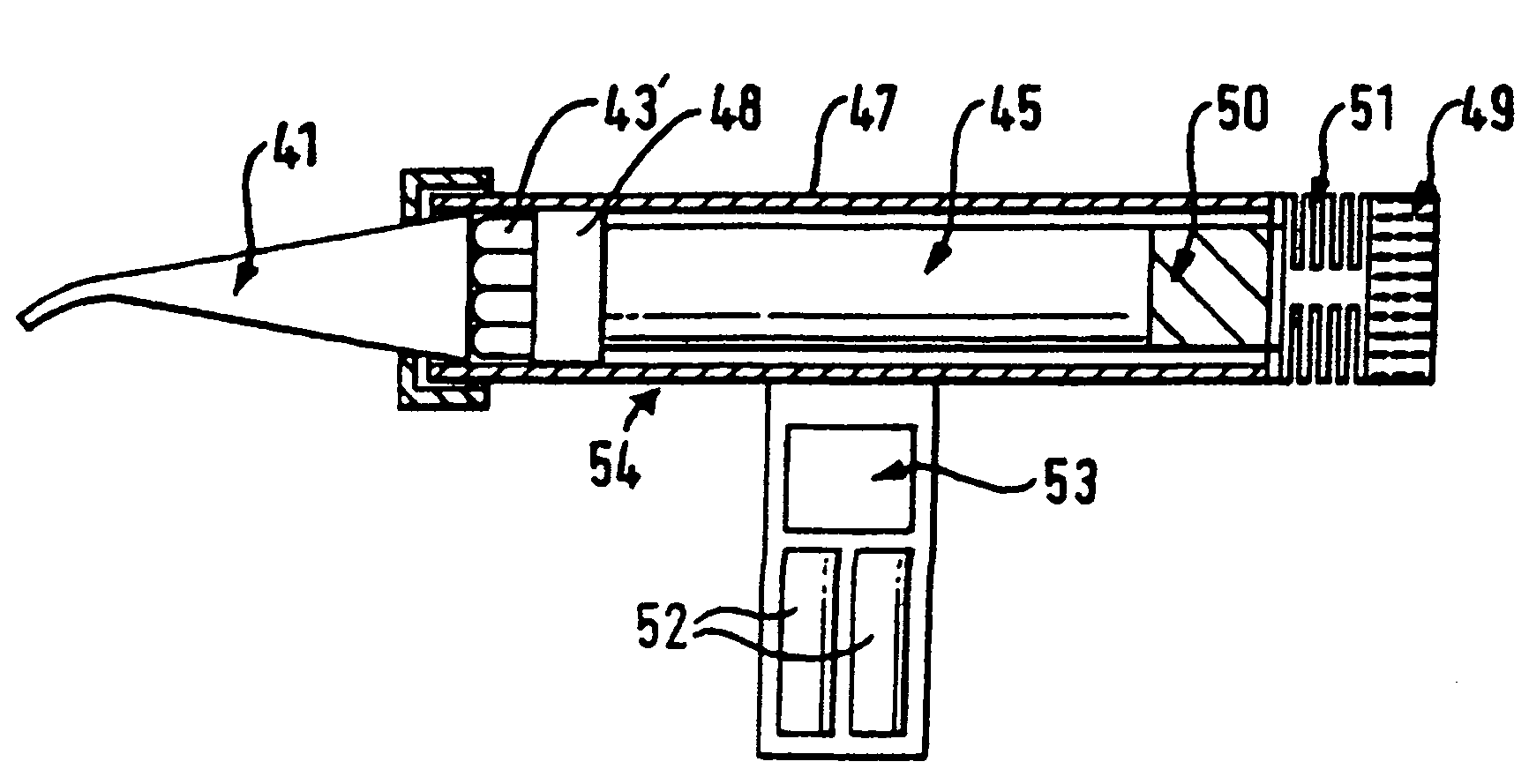
[0003]An object of the present invention is to provide an optical irradiation device that employs LEDs, and thereby has the benefits of compactness, portability, ruggedness and long life, but which also produces improved levels of irradiance at and above 300 mW / sq.cm.
[0009]The first aspect of the invention means that LEDs occupy more of the available space, and a fixed number produce a higher radiant intensity. Thus, smaller numbers of LEDs can be used to produce a desired level of irradiance, which in turn reduces the power required to drive the device and the heat generated by it. Furthermore, the device can be made more compact. Packing of the LEDs in this way may involve a slight reduction in the output of each LED, but the more effective packing density produces an overall increase in irradiance.

Problems solved by technology

However, there is a problem in producing a sufficient level of irradiance even with a clustered array of LEDs, to cure the known dental polymers in the recommended time.
At the lower levels of irradiance available generally below 300 mW / sq.cm, longer curing times have to be allowed, which reduces the efficiency of the dental treatment delivered.

Method used


Image

  • Optical irradiation device having LED and heat pipe
  • Optical irradiation device having LED and heat pipe
  • Optical irradiation device having LED and heat pipe

Examples


second embodiment

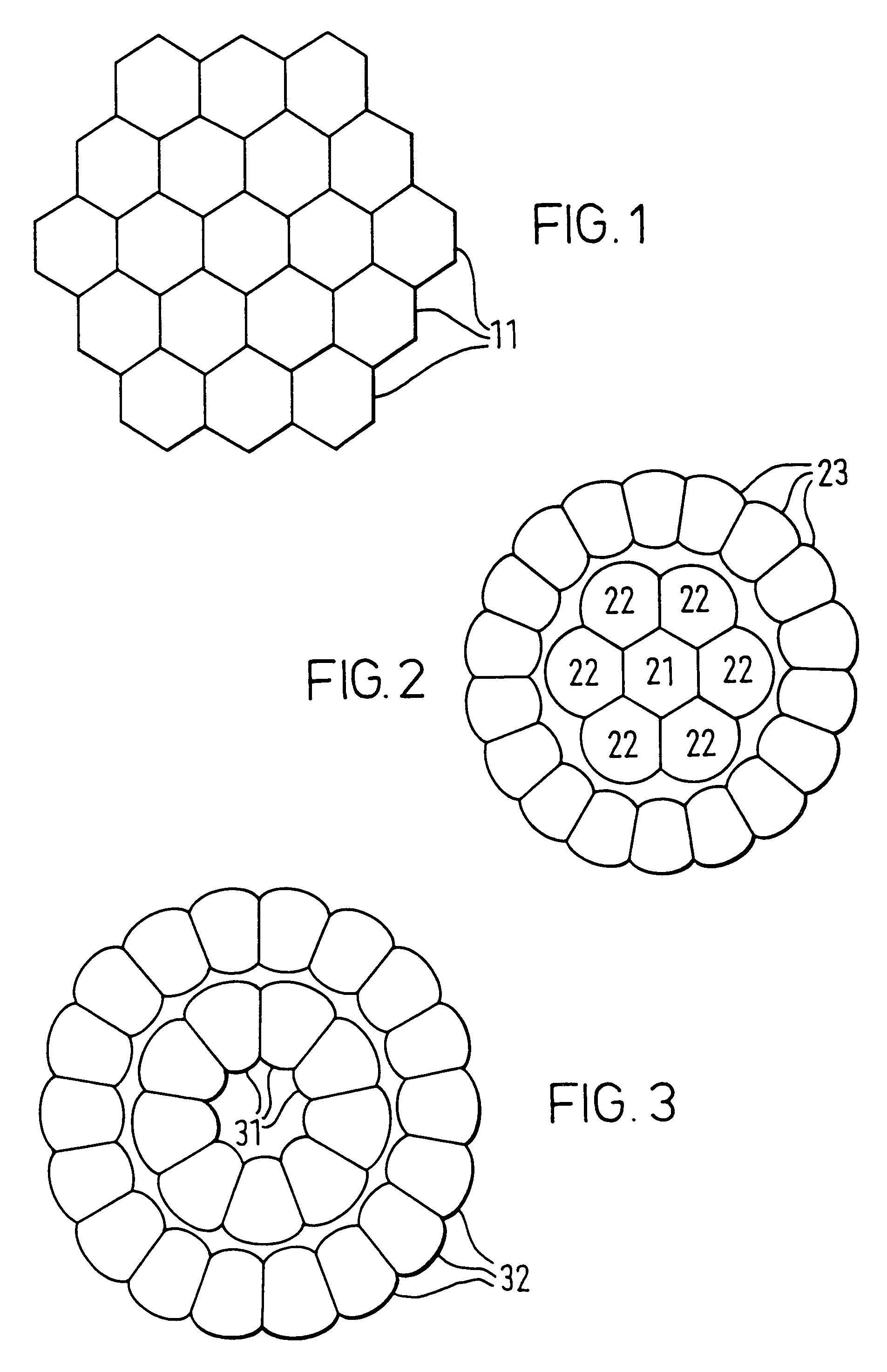
[0023]In the invention illustrated in FIG. 2, a central LED 21 of hexagonal cross-section has facets which abut adjacent facets of six LEDs 22 in a first ring of LEDs with radially extending side facets that allow adjacent LEDs in the ring to abut one another. A second ring of LEDs 23 is arranged around the first ring of LEDs, and these LEDs 23 have radially extending side facets that allow adjacent LEDs in the ring to abut one another.

third embodiment

[0024]In the invention shown in FIG. 3, an inner ring of nine LEDs 31 in a first ring is contained within a second ring of LEDs 32, and radially extending side facets of the LEDs in both rings allow adjacent LEDs in each ring to abut one another.

[0025]Both the second embodiment of FIG. 2 and the third embodiment of FIG. 3 may be modified by the addition of one or more further concentric rings of LEDs. Also, the circumferential facets of the LEDs of each ring may be shaped to abut similarly shaped circumferential facets of the adjacent ring of LEDs.

[0026]In yet another embodiment, the central group of LEDs 21,22 of FIG. 2 may be replaced by the same number of LEDs in a honeycomb cluster. Yet another embodiment may consist of the single ring of LEDs 31 shown in FIG. 3. It will be appreciated in all three illustrated embodiments, the LEDs are mounted in a substantially flat plane.

[0027]In modifying the conventional optical sphere shape of the outer plastics envelope of a LED care has t...


PUM


Abstract

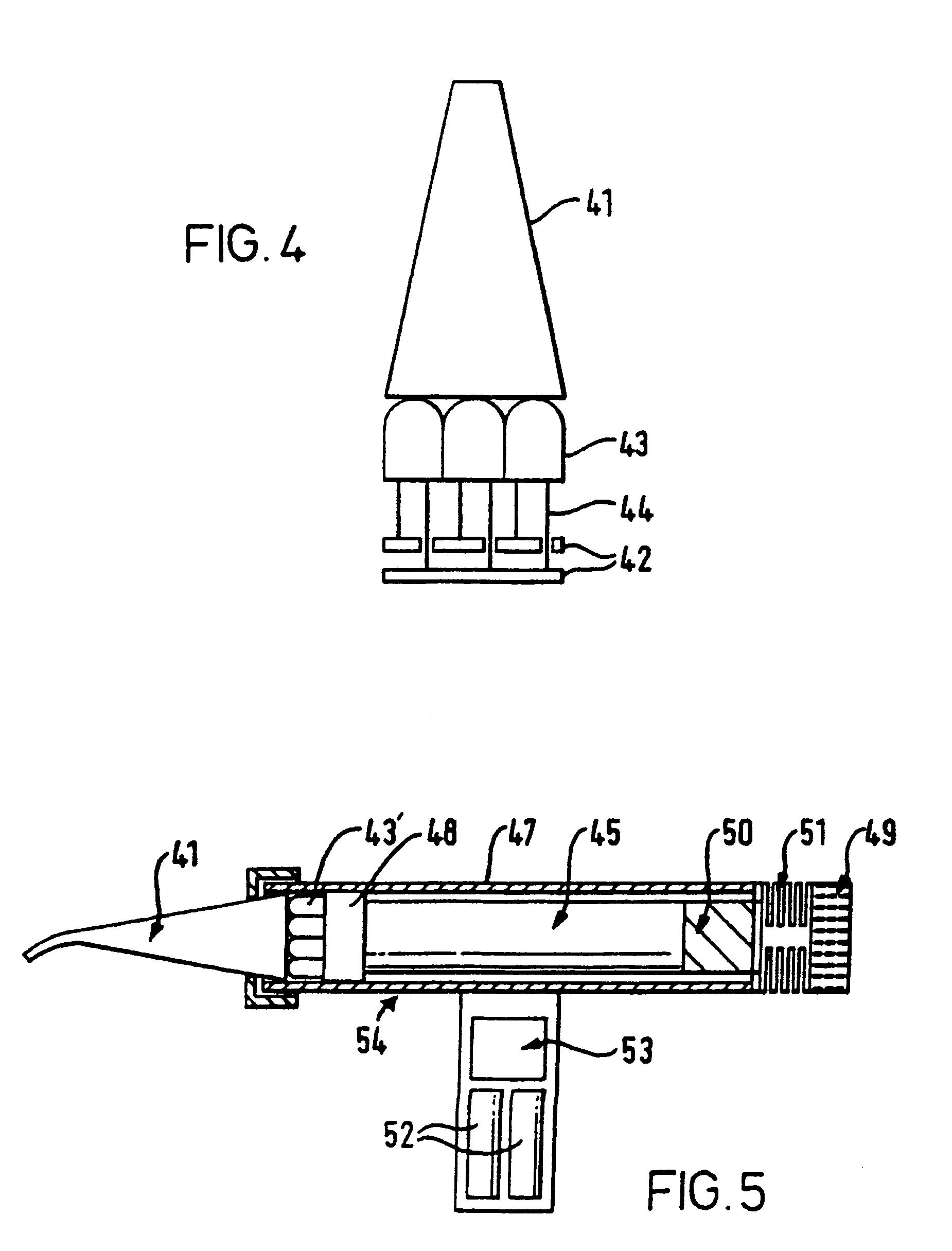
An optical irradiation device incorporating a plurality of LEDs arranged in one or more clusters or arrays. A heat pipe is provided to conduct heat away from the LEDs allowing the LEDs to be driven to produce more radiation than would be possible without the heat pipe.

Description

TECHNICAL FIELD[0001]This invention relates to an optical irradiation device, especially a compact portable irradiation device suitable for use as a light polymerisation source.[0002]It has already been proposed to use light-emitting diodes LEDs in a hand held device to produce a focused beam of light to cure dental materials. Blue light at a peak wavelength of about 470 nm is used to harden dental polymers which contain camphoroquinone as the photoinitator in a methacrylate polymerisation process. However, there is a problem in producing a sufficient level of irradiance even with a clustered array of LEDs, to cure the known dental polymers in the recommended time. At the lower levels of irradiance available generally below 300 mW / sq.cm, longer curing times have to be allowed, which reduces the efficiency of the dental treatment delivered.DISCLOSURE OF THE INVENTION[0003]An object of the present invention is to provide an optical irradiation device that employs LEDs, and thereby has...

Claims


Application Information

Patent Timeline
Patent Type & Authority Patents(United States)
IPC IPC(8): F21V29/00F28D15/02A61C13/15A61N5/06G02B6/42H01L25/13
CPCA61C19/004A61N5/0601A61N5/062A61N2005/0652G02B6/4298Y10S362/80
Inventor MILLS, ROBIN WALTERJANDT, KLAUS DIETER
Owner SIGNIFY HLDG BV
Learn More