Centrifugal separator having a rotor and driving means thereof

a centrifugal separator and driving means technology, applied in centrifuges, separation processes, auxillary pretreatment, etc., can solve the problems of inefficient and compact arrangement of centrifugal rotor operation of gas turbines, and achieve the effect of maximizing space and facilitating operation

Inactive Publication Date: 2006-04-04
ALFA LAVAL CORP AB
View PDF10 Cites 41 Cited by
  • Summary
  • Abstract
  • Description
  • Claims
  • Application Information

AI Technical Summary

Benefits of technology

[0010]A driving means of this kind can be made efficient, because the energy of the driving fluid can be utilised in an advantageous way, and also be made compact because the driving means can be integrated with the rotor itself.
[0011]Even if it is possible to arrange the supply member for the driving fluid so that it directs the driving fluid axially towards the turbine members, it is assumably most advantageous to arrange one of the supply member and the reversing member radially outside the ring of turbine members and the other one of the supply member and the reversing member radially inside the ring of the turbine members. It is assumed that the available space would be utilised most effectively if the supply member is arranged radially outside and the reversing member radially inside said ring of turbine members.
[0012]If two or more supply members and reversing members are used, it is suitable that these are distributed evenly around the ring of turbine members, so that a balanced loading of the rotor is obtained from the forces to which this is subjected by the driving fluid. If only two supply members and reversing members, respectively, are used these are, thus, arranged at diametrically opposite sides of the ring of turbine members. This is advantageous for the life time of the bearings, through which the rotor is suspended in a stationary support device, e.g. a housing surrounding the whole rotor.

Problems solved by technology

However, no efficient and compact arrangement for gas turbine operation of a centrifugal rotor has been seen.

Method used


Image

  • Centrifugal separator having a rotor and driving means thereof
  • Centrifugal separator having a rotor and driving means thereof
  • Centrifugal separator having a rotor and driving means thereof

Examples


Embodiment Construction

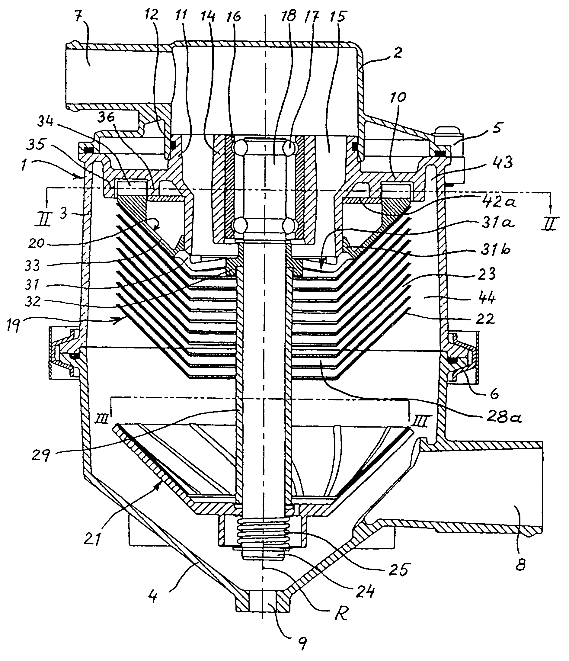
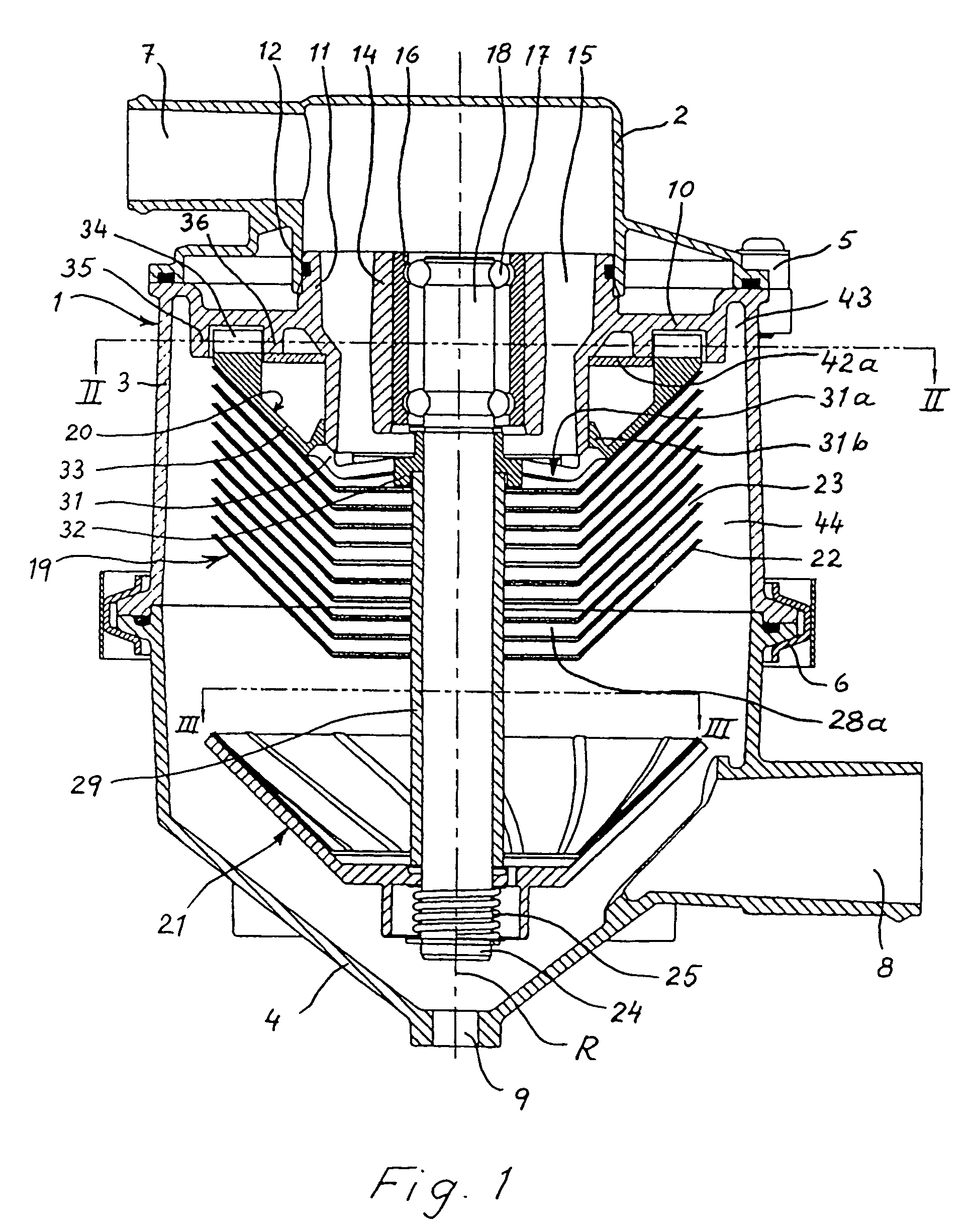
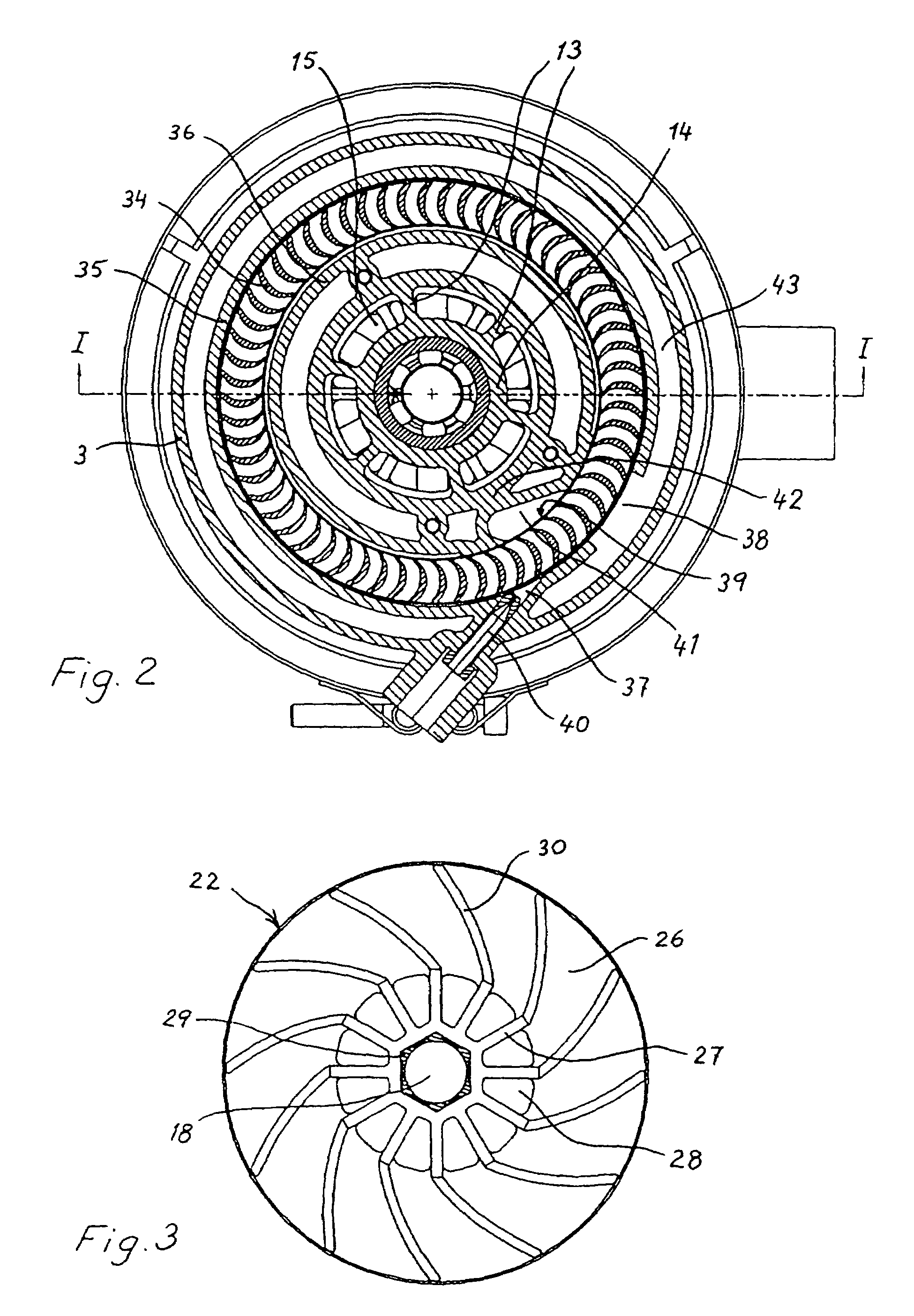
[0018]The centrifugal separator shown in the drawing includes a stationary housing 1 consisting of an upper part 2, an intermediate part 3 and a lower part 4. The parts are kept together by means of clamping members 5 and 6. The upper housing part 2 forms an inlet 7 for a gas or a gas mixture to be cleaned by means of the centrifugal separator. The lower housing part 4 forms both an outlet 8 for gas having been cleaned and an outlet 9 for material having been separated from the gas.

[0019]The intermediate part 3 of the stationary housing forms a surrounding wall, surrounding a space in the housing, and has at its upper end an annular end wall 10 extending a distance inwardly from the surrounding wall. The annular end wall 10 supports within the housing a central sleeve 11, the interior of which communicates with the aforementioned gas inlet 7, that is formed by the upper housing part 2. A gasket 12 is adapted to seal between the upper housing part 2 and the sleeve 11.

[0020]The sleeve...


PUM

PropertyMeasurementUnit
distanceaaaaaaaaaa
radial distanceaaaaaaaaaa
areaaaaaaaaaaa

Abstract

In a centrifugal separator, the rotor of which is adapted to be driven by means of a gaseous driving fluid, the rotor itself supports a ring of turbine blades extending around the rotational axis of the rotor. A stationary nozzle is adapted to direct a flow of the driving fluid towards the ring of turbine members. After the driving fluid has passed between the turbine blades and has influenced them for driving of the centrifugal rotor, it enters a reversing chamber formed by a stationary reversing member. In the reversing chamber the driving fluid is caused to change its direction and is then conducted again towards the ring of turbine members in order to be utilized a second time for driving of the centrifugal rotor.

Description

CROSS-REFERENCE TO RELATED APPLICATIONS[0001]This application is a continuation of International Application No. PCT / SE01 / 02284 filed on Oct. 19, 2001, which designates the United States of America and was published in English as PCT International Publication No. WO 02 / 34408 A1 on May 2, 2002, and Swedish Patent Application No. 0003915-6 filed on Oct. 27, 2000. The disclosures of these patent applications are incorporated by reference herein in their entireties.FIELD OF THE INVENTION[0002]The present invention relates to a centrifugal separator having a rotor and a driving means for rotation of the rotor about a rotational axis by means of a gaseous driving fluid.BACKGROUND OF THE INVENTION[0003]About 100 hundred years ago pressurised steam was sometimes used for driving centrifugal rotors. A steam turbine was coupled to the driving shaft of a centrifugal rotor in one way or another, usually through a gear device. Since then rotors of high speed separators usually have been driven b...

Claims


Application Information

Patent Timeline
Patent Type & Authority Patents(United States)
IPC IPC(8): B01D45/14B01D53/06B04B5/00B04B5/08B04B5/12B04B9/06F01D1/12F01D1/14
CPCB04B5/005B04B5/08B04B5/12F01D1/14F01D1/12B04B9/06B04B2005/125
Inventor BORGSTROM, LEONARDCARLSSON, CLAES-GORANFRANZEN, PETERINGE, CLAESLAGERSTEDT, TORGNYMOBERG, HANSSZEPESSY, STEFAN
Owner ALFA LAVAL CORP AB
Why Eureka
Try Eureka