Hybrid aerial and terrestrial vehicle

Active Publication Date: 2014-05-15
ILLINOIS INSTITUTE OF TECHNOLOGY
View PDF19 Cites 115 Cited by
  • Summary
  • Abstract
  • Description
  • Claims
  • Application Information

AI Technical Summary

Benefits of technology

[0014]The invention has a simple design. This makes it easy and low cost to manufacture. The flying system does not have a new or specific design requirement. Any regular flying rotorcraft system, for which there are many well developed samples available, can be employed as the flying agent. The rolling cage is desirably impact resistance and durable against the shocks that aggressive landings or crashes of the flying device can cause. I

Problems solved by technology

When an obstacle is encountered,

Method used


Image

  • Hybrid aerial and terrestrial vehicle
  • Hybrid aerial and terrestrial vehicle
  • Hybrid aerial and terrestrial vehicle

Examples


Embodiment Construction

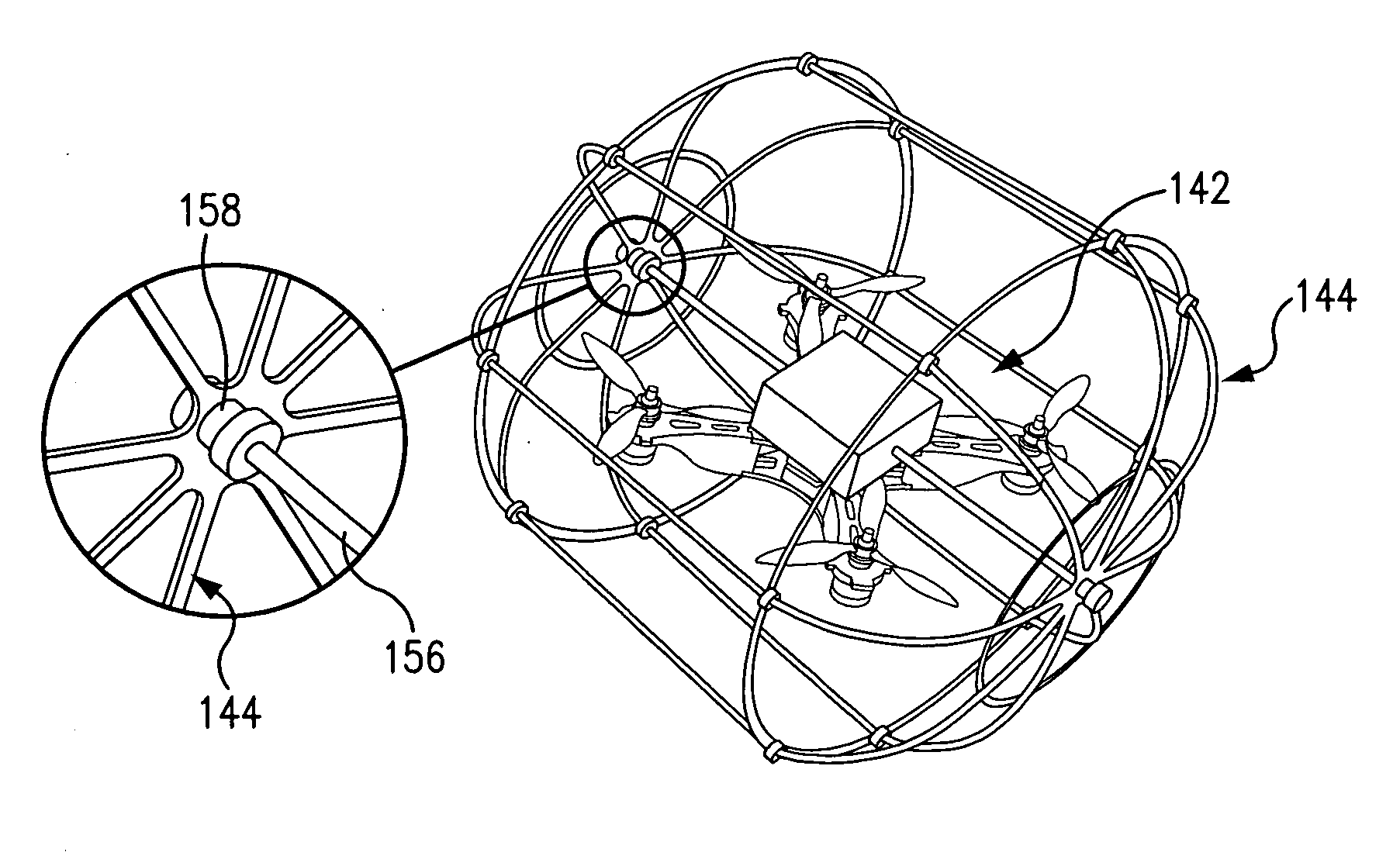
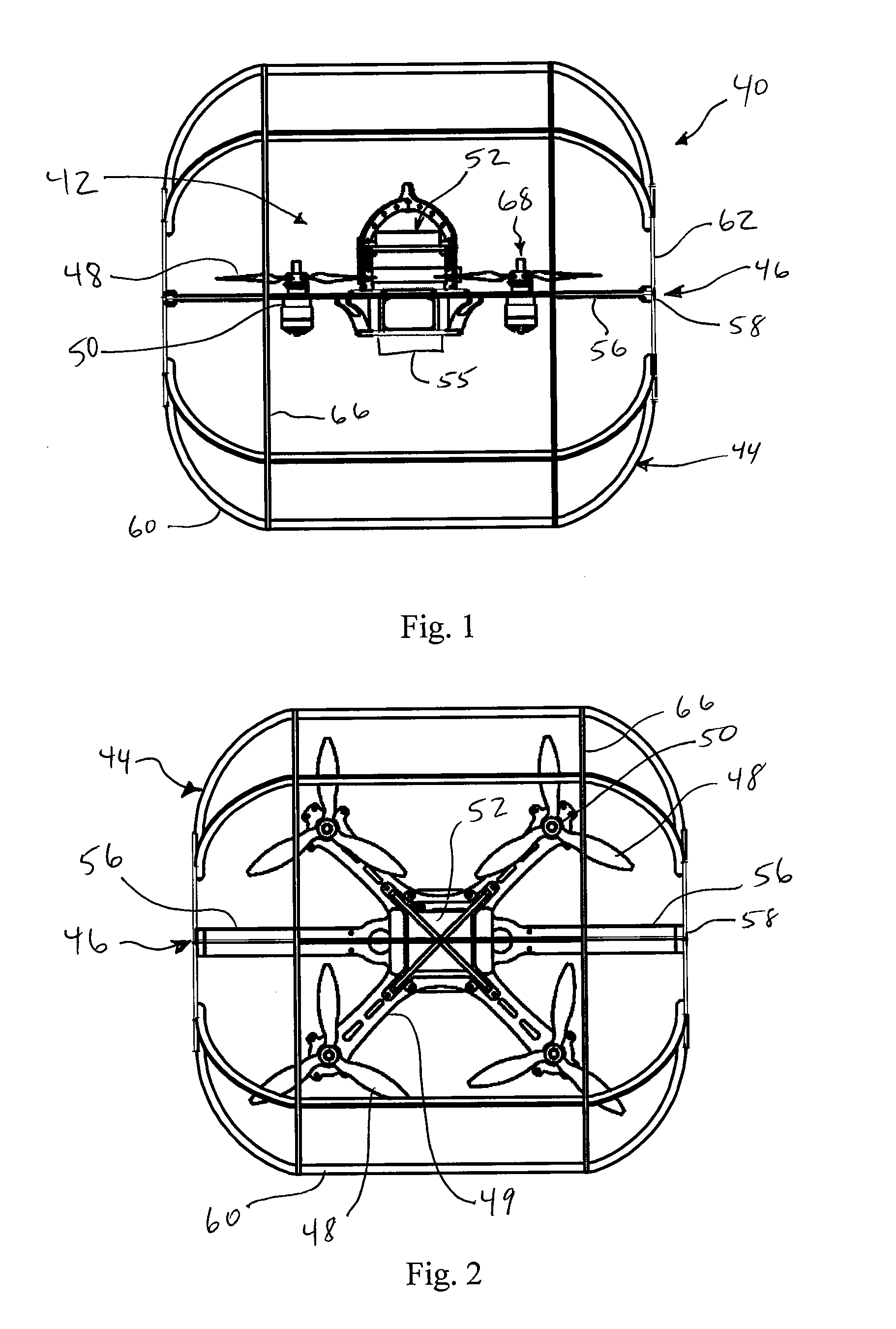
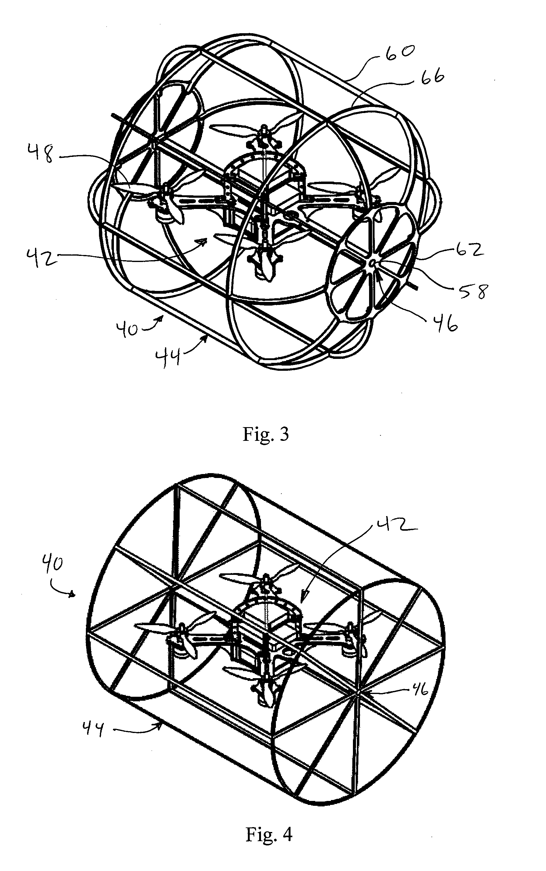
[0032]This invention provides a mobile autonomous or remote-controlled vehicle, such as a MAV, capable of both aerial and terrestrial locomotion. Flight is desirably achieved through a suitable rotor configuration, such as a quadrotor with four actuators that provide the required thrust. Adding a non-powered rolling cage to the vehicle makes terrestrial locomotion possible using the same actuator set and control system. Thus, neither the mass nor the system complexity is increased by inclusion of separate actuators for terrestrial and aerial locomotion. An analysis of the system's energy consumption demonstrated that during terrestrial locomotion, the vehicle only needs to overcome rolling resistance and consumes much less energy compared to the aerial mode. This solves one of the most vexing problems of quadrotors and rotorcraft in general, namely their short operation time. Experimental results showed that the hybrid vehicle can travel a distance four times greater and operate alm...


PUM


Abstract

A vehicle capable of both aerial and terrestrial locomotion. The terrestrial and aerial vehicle includes a flying device and a rolling cage connected to the flying device by at least one revolute joint. The rolling cage at least partially surrounds the flying device and is free-rolling and not separately powered.

Description

CROSS REFERENCE TO RELATED APPLICATION[0001]This application claims the benefit of U.S. Provisional Application, Ser. No. 61 / 726,335, filed on 14 Nov. 2012. The co-pending provisional application is hereby incorporated by reference herein in its entirety and is made a part hereof, including but not limited to those portions which specifically appear hereinafter.[0002]This invention was made with government support under award N00014-10-1-0769 awarded by Office of Naval Research. The government has certain rights in the invention.BACKGROUND OF THE INVENTION[0003]1. Field of the Invention[0004]This invention is directed to an unmanned vehicle, and more particularly to an autonomous or remotely controlled vehicle capable of both aerial and terrestrial locomotion.[0005]2. Discussion of Related Art[0006]The ability to quickly reach a goal location without needing to navigate obstacles or challenging terrain makes aerial vehicles an excellent choice in applications like search and rescue ...

Claims


Application Information

Patent Timeline
IPC IPC(8): B60F5/02
CPCB60F5/02B64C39/024A63H33/005A63H27/12B64U10/13B64U50/19B64C25/36B64C39/028B64U2101/30B64C37/00
Inventor KALANTARI, ARASHSPENKO, MATTHEW
Owner ILLINOIS INSTITUTE OF TECHNOLOGY
Why Eureka
Try Eureka